Vehicle having air-guiding arrangement

A guiding device and vehicle technology, applied in the field of vehicles, can solve problems such as unfavorable aerodynamics of the vehicle floor

Active Publication Date: 2017-02-22
BAYERISCHE MOTOREN WERKE AG
View PDF5 Cites 1 Cited by
  • Summary
  • Abstract
  • Description
  • Claims
  • Application Information

AI Technical Summary

Problems solved by technology

In addition, an aerodynamically unfavorable situation arises due to the turbulent incoming flow to the vehicle floor located downstream of the air guiding device.

Method used


Image

  • Vehicle having air-guiding arrangement
  • Vehicle having air-guiding arrangement
  • Vehicle having air-guiding arrangement

Examples


Embodiment Construction
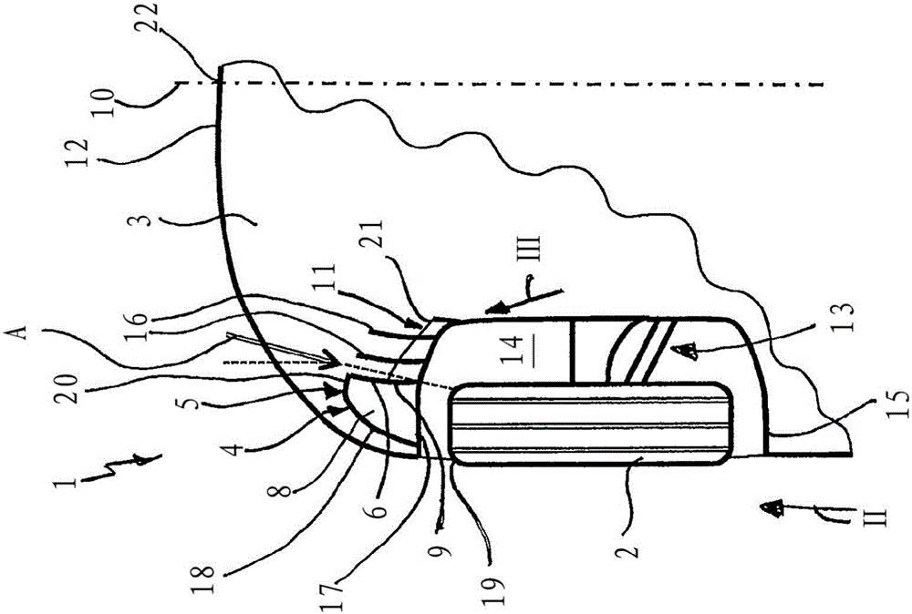
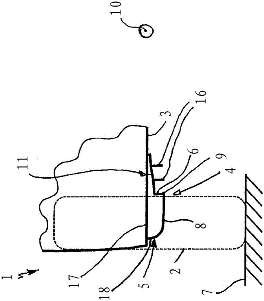
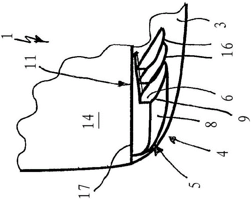
[0029] figure 1 The front area of ​​vehicle 1 or motor vehicle including wheels 2 is shown. An air guiding device 4 comprising a first air guiding body 5 is arranged on the underside 3 of the vehicle 1 . The three-dimensional and hollow air guide body 5 has the same figure 2 and image 3 The guide surface 6 shown in the drawing is arranged to run at least approximately at right angles to the underside 3 of the vehicle in the exemplary embodiment shown in the figures and is referred to below as the lateral region 6 . The lateral area 6 adjoins a floor area 8 facing the ground 7 which is spaced apart from the underside 3 of the vehicle. In the abutment region between the lateral region 6 and the floor region 8 there is provided an edge 9 extending substantially in the longitudinal direction of the vehicle, which edge establishes the flow formed by the first air-guiding body 5 with respect to the center of the vehicle 10 next to the lateral region 6 . The separation of the r...


PUM


Abstract

A vehicle (1) having an air-guiding device (4) arranged on a lower side (3) of the vehicle (1) in front of a vehicle wheel (2) is described. The air-guiding device (4) comprises an air-guiding body (5) which has a side region (6) running substantially in the vertical direction of the vehicle and facing a vehicle centre (10), and a bottom region (8) which faces an underlying surface (7) and is connected to the side region (6) and is spaced apart from the lower side (3). In an outer region (18) of the air-guiding body (5), which faces away from the vehicle centre (10) and is connected to the bottom region (8) and is formed with a convex curvature with respect to the outer side of the vehicle, an air flow can be directed in the direction of an outer flank (19) of the vehicle wheel, while an air flow can be oriented in the longitudinal direction of the vehicle via the guiding surface (6).

Description

technical field [0001] The invention relates to a vehicle of the type defined in detail in the preamble of claim 1 , comprising an air guiding device arranged on the underside of the vehicle in front of the wheels. Background technique [0002] An air guide for a vehicle is known from EP 1674381 B1, which is arranged in the area in front of the wheels and protrudes downwards in the direction of the roadway. The air guiding device has an air guiding body which is convexly curved on its front side facing away from the wheel and which has a separating edge on at least one partial area of ​​its free end section in order to reduce the force acting on the wheel. Flow pressure and reduce the overall air resistance of the vehicle. The mode of action of the air guiding device constitutes a so-called flow separation of not only the rotating wheel but also the corresponding associated axle geometry. A dead zone is created in the flow downstream of the air guiding device, which potent...

Claims


Application Information

Patent Timeline
Patent Type & Authority Applications(China)
IPC IPC(8): B62D35/02B62D37/02
CPCB62D35/02B62D37/02Y02T10/88Y02T10/82B62D35/005B62D35/008
Inventor G·特施M·福泽
Owner BAYERISCHE MOTOREN WERKE AG
Why Eureka
Try Eureka