Eureka AIR delivers breakthrough ideas for toughest innovation challenges, trusted by R&D personnel around the world.

Soi wafer manufacturing method

一种制造方法、芯片的技术,应用在半导体/固态器件制造、电气元件、电固体器件等方向,达到膜厚均匀性高、抑制导电型和电阻率等的变动的效果

Active Publication Date: 2010-03-24
SHIN-ETSU HANDOTAI CO LTD
View PDF2 Cites 5 Cited by
  • Summary
  • Abstract
  • Description
  • Claims
  • Application Information

AI Technical Summary

Problems solved by technology

[0010] The same problem, for example, even in the case of using other thinning methods such as grinding and grinding, after thinning, the heat treatment for thickening the SOI layer by performing epitaxial growth on the SOI layer and the use of SOI chips Occurs due to heat treatment in the component manufacturing process

Method used


Image

  • Soi wafer manufacturing method
  • Soi wafer manufacturing method
  • Soi wafer manufacturing method

Examples


Embodiment 1~4

[0102] (Examples 1 to 4, Comparative Examples 1 and 2)

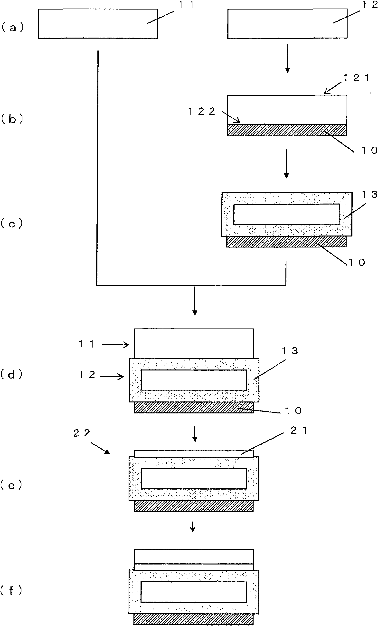
[0103] use figure 1 Fabrication of the SOI chip 22 is carried out using the flow shown. The main production conditions and results at this time are shown in Table 1 and explained below.

[0104] [Table 1]

[0105]

[0106]

[0107] First, as the bonding chip 11, prepare a 200 mm in diameter, phosphorus-doped n-type single crystal silicon chip, and as the base chip 12, prepare a 200 mm in diameter, p-type, boron-doped (6×10 18 atoms / cm 3 ) of p + Single crystal silicon chips (Examples 1 to 4, Comparative Examples 1 and 2).

[0108] Next, place the base chip 12 on the receiving body of the CVD furnace with the bonding surface 121 facing down, and form a CVD oxide layer as the CVD insulating film 10 on the opposite surface 122 by the CVD method. membrane. The thickness of the formed CVD oxide film was 100nm in Example 1, 200nm in Example 2, 300nm in Example 3, and 500nm in Example 4. In addition, in Comparat...


PUM


Abstract

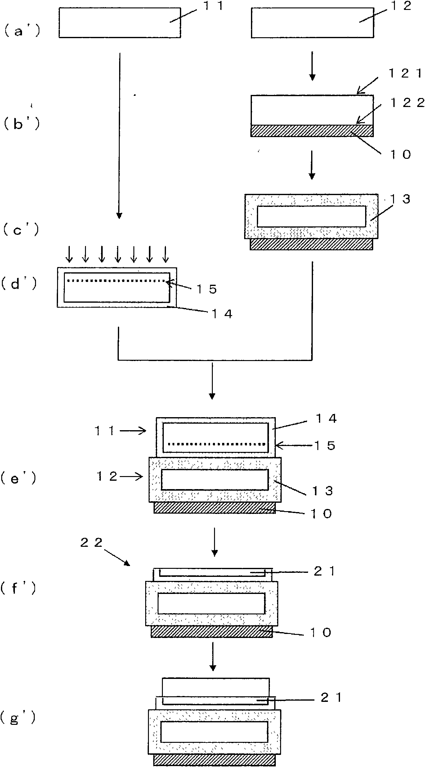
An SOI wafer manufacturing method includes a step of preparing a base wafer, which is composed of a p+ silicon single crystal wafer, and a bond wafer, which is composed of a silicon single crystal wafer containing a dopant at a concentration lower than that in the base wafer; a step of forming a silicon oxide film over the entire surface of the base wafer by thermal oxidation; a step of bonding the bond wafer and the base wafer through a silicon oxide film; and a step of forming an SOI layer by thinning the bond wafer. The SOI wafer manufacturing method is characterized in having a step of forming a CVD insulating film on a surface on the opposite side to the bonding surface of the base wafer, prior to the base wafer thermal oxidation step. Thus, the p-type dopant contained in the base wafer is easily prevented from diffusing outward from the surface opposite to the bonding surface of the base wafer due to high-temperature heat treatment, mixing of the p-type dopant in the SOI layer issuppressed and warping can be reduced.

Description

technical field [0001] The present invention relates to a method for manufacturing a silicon on insulator (SOI) chip, in particular to a method for manufacturing an SOI chip. They are bonded through an oxide film, and then the bonded chip is thinned to produce an SOI chip. Background technique [0002] As one of chips for semiconductor elements, there is an SOI (Silicon on Insulator) chip in which a silicon layer (hereinafter sometimes referred to as an SOI layer) is formed on a silicon oxide film that is an insulating film. In this SOI chip, the SOI layer on the surface of the substrate in the device fabrication region is electrically separated from the inside of the substrate by embedding an insulating layer (buried oxide layer (BOX layer)), so it has low parasitic capacitance and high radiation resistance. Characteristics. Therefore, effects such as high-speed, low-power-consumption operation, and prevention of soft errors can be expected, and it is considered promising...

Claims


Application Information

Patent Timeline
Patent Type & Authority Applications(China)
IPC IPC(8): H01L21/02H01L21/223H01L27/12
CPCH01L21/76256H01L21/02H01L21/223H01L27/12
Inventor 横川功竹野博能登宣彦
Owner SHIN-ETSU HANDOTAI CO LTD
Why Eureka
Eureka Blog
Learn More