
Polyolefin microporous membrane

A technology made of microporous membranes and polyolefins, applied to secondary battery parts, structural parts, battery pack parts, etc., can solve problems such as insufficient electrical characteristics, difficulty in achieving high membrane strength, and increased thermal shrinkage problems, achieve excellent strength and low heat shrinkage, improve battery characteristics and battery safety

Active Publication Date: 2009-10-28
ASAHI KASEI KK
View PDF3 Cites 12 Cited by
  • Summary
  • Abstract
  • Description
  • Claims
  • Application Information

AI Technical Summary

Problems solved by technology

However, the film produced through this extraction and stretching process not only has a tendency to increase the thermal shrinkage rate, but also under the water permeability / air permeability described in this document, the lithium ion secondary battery with high output power in recent years In batteries, etc., the electrical characteristics often become insufficient
[0008] In Patent Document 3, a microporous membrane with a large pore size prepared by using a high molecular weight polyolefin is proposed. However, a so-called microporous membrane with high heat resistance, high strength, large pore size, and excellent balance has not been obtained so far.
[0009] In addition, in Patent Document 4, a microporous membrane with high heat resistance and large pore diameter is proposed. However, it is difficult to achieve high strength of the membrane by this method.
[0010] In addition, in Patent Document 5, a high-strength microporous film prepared using a specific polyolefin mixture is proposed, however, since low-density polyethylene is blended, heat fixation at high temperatures becomes difficult

Method used

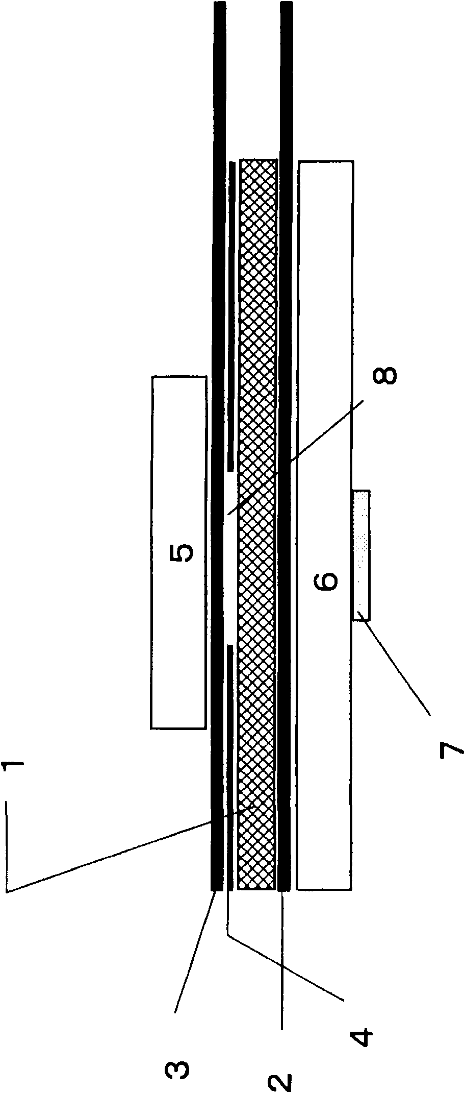

Image

  • Polyolefin microporous membrane
  • Polyolefin microporous membrane

Examples


Embodiment 1

[0137] 47% by mass of Mv700,000 homopolymer polyethylene, 46% by mass of Mv300,000 homopolymer polyethylene, and 7% by mass of Mv400,000 polypropylene were dry blended using a tumble mixer. 1% by mass of pentaerythritol-tetrakis[3-(3,5-di-tert-butyl-4-hydroxyphenyl)propionate] was added as an antioxidant to 99% by mass of the pure polymer mixture obtained, Dry blending was performed again with a drum mixer to obtain a mixture of polymers and the like. The mixture of the obtained polymer and the like was replaced with nitrogen, and then supplied to a twin-screw extruder through a feeder under a nitrogen atmosphere. In addition, liquid paraffin (dynamic viscosity at 37.78°C is 7.59×10 -5 m 2 / s) into the extruder barrel.

[0138] The feeder and the pump were adjusted so that the ratio of the amount of liquid paraffin to the entire mixture of melt kneading and extrusion was 65% by mass. The melt-kneading conditions were a set temperature of 200° C., a screw rotation speed of ...

Embodiment 2

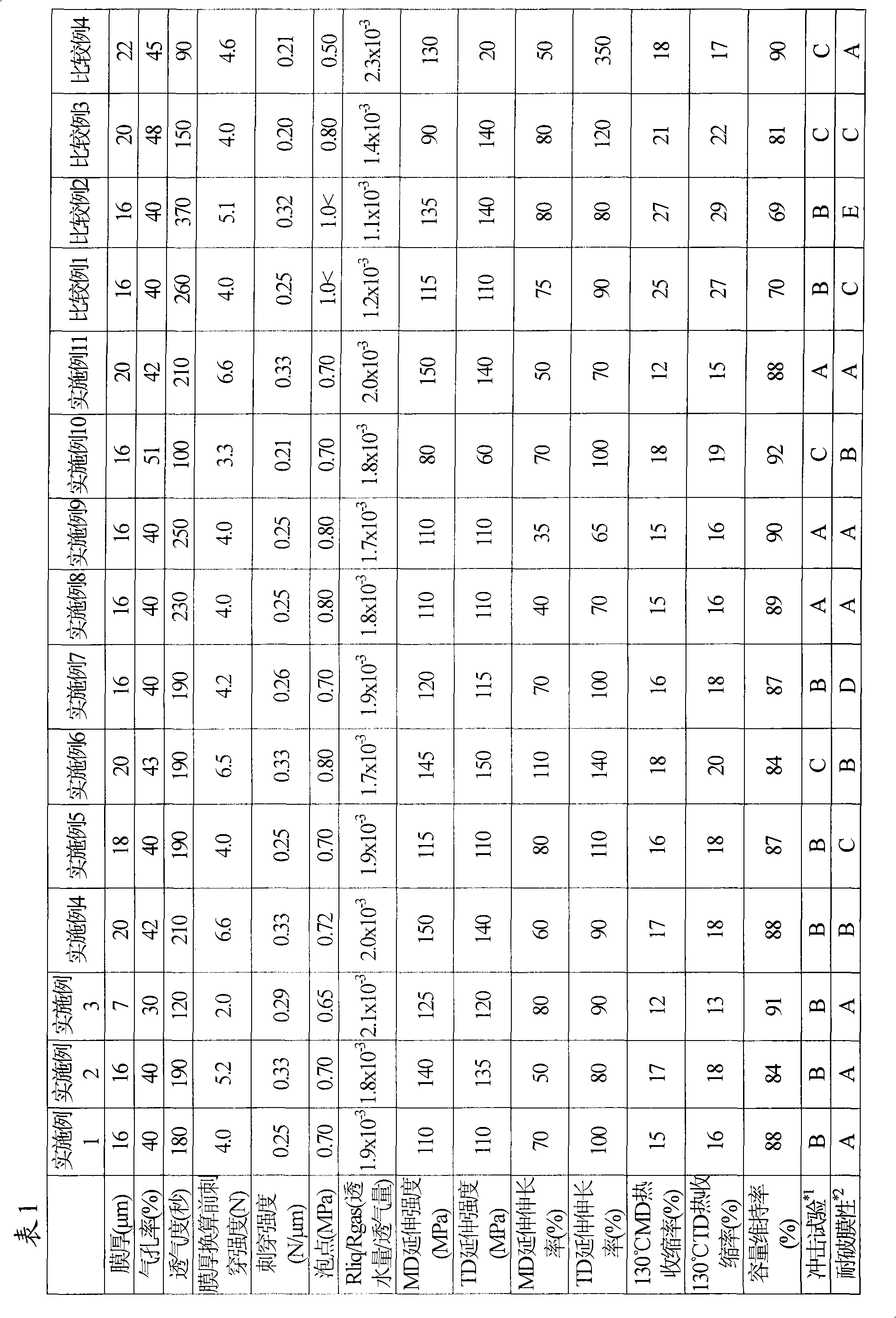
[0145] Except that the biaxial stretching temperature was 120° C., it was carried out in the same manner as in Example 1. Table 1 shows the physical properties of the obtained polyolefin microporous membrane.

Embodiment 3

[0147] Except that the original film thickness after extrusion is 900 μm, the biaxial stretching temperature is 122°C, the stretching temperature at the time of heat setting is 130°C, and the stretching ratio is 2.0 times, and the temperature at the time of relaxation thereafter is 135°C and the relaxation rate is 0.80. Other than that, it carried out similarly to Example 1. Table 1 shows the physical properties of the obtained polyolefin microporous membrane.


PUM

PropertyMeasurementUnit
Dynamic viscosityaaaaaaaaaa
Thicknessaaaaaaaaaa
Thicknessaaaaaaaaaa

Abstract

Disclosed is a polyolefin microporous membrane having a bubble point of not more than 1 MPa, a tensile strength in the longitudinal direction of not less than 50 MPa, a tensile strength in the width direction of not less than 50 MPa, and a thermal shrinkage in the width direction at 130 DEG C of not more than 20%. This polyolefin microporous membrane is excellent in strength and low thermal shrinkage property, while having a large pore diameter.

Description

technical field [0001] The present invention relates to microporous membranes widely used as separation membranes for material separation and selective permeation, separators for electrochemical reaction devices such as alkaline secondary batteries, lithium secondary batteries, fuel cells, and capacitors. In particular, the present invention relates to a polyolefin microporous membrane suitable as a separator for lithium ion batteries. Background technique [0002] Microporous membranes made of polyolefins are widely used as separation and selective permeation separation membranes and separator materials for various substances. Base materials for functional films that fill pores with materials to express new functions, separators for batteries, etc. Among these uses, it is particularly preferably used as a separator for lithium ion batteries widely used in notebook personal computers, mobile phones, digital cameras, and the like. The reason for this is that such a membrane...

Claims


Application Information

Patent Timeline
IPC IPC(8): C08J9/00H01M2/16H01M50/417H01M50/489H01M50/491H01M50/494
CPCY02E60/12H01M2/1653H01M10/052Y02E60/10H01M50/417H01M50/491H01M50/489H01M50/494C08J9/22H01M10/02C08L23/02H01M50/403
Inventor 稻垣大助武田久
Owner ASAHI KASEI KK
Learn More