Diffuser with base coat and manufacturing method thereof, laminated optical component, surface light source device and liquid crystal display device
A technology of a light diffusion plate and a manufacturing method, which is applied to optical elements, optics, lighting devices, etc., and can solve problems such as increased equipment costs, decreased productivity, and easy retention of primer liquid
- Summary
- Abstract
- Description
- Claims
- Application Information
AI Technical Summary
Problems solved by technology
Method used
Image


Examples
Embodiment 1
[0153] (Manufacture of light diffusing agent masterbatch)
[0154] Styrene resin particles ("HRM40" manufactured by Toyo Styrene Co., Ltd., refractive index: 1.59) 54 parts by weight, acrylic polymer particles (cross-linked polymer particles, "Sumitomo XC1A" manufactured by Sumitomo Chemical, refractive index: 1.49, volume average particles 40 parts by weight of siloxane-based polymer particles (cross-linked polymer particles, Toray Dow Corning "Trefil DY33-719", refractive index 1.42, volume average particle diameter 2 μm) 4 parts by weight, heat stabilizer (Sumitomo Chemical Co., Ltd. "Sumiソライブ-200", powder form) 2 parts by weight, and processing stabilizer (Sumitomo Chemical Co., Ltd. "Sumila Iza-GP", powder form) 2 parts by weight dry-mixed, put into two parts from the hopper Using a shaft extruder, heat and melt while mixing, extrude at 250° C. into strands, and cut into pellets to obtain light diffusing agent masterbatch (granules).
[0155] (manufacture of coarse parti...
Embodiment 2
[0162] In addition to using 7.5 parts by weight of "Carbodilite V02-L2" (trade name) manufactured by Nisshinbo Co. Except for the primer liquid mixed, it carried out similarly to Example 1, and obtained the light-diffusion plate.
Embodiment 3
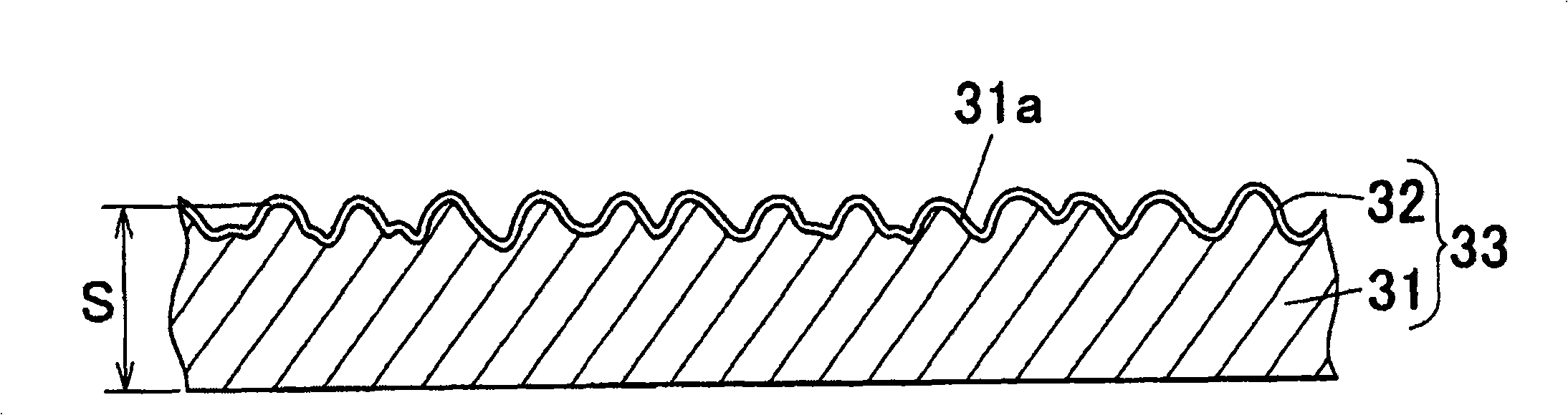
[0164] By melt extrusion transfer molding using an engraved roll (engraved roll), protruding and forming a plurality of cylindrical lens-shaped convex lines on the entire surface of one surface, thereby manufacturing a surface (31a) in which one surface is formed with concavities and convexities. A synthetic resin light diffusion plate (31) with a thickness of 2 mm (refer to Image 6 ). In this light diffusion plate (31), the height (H) of the approximately semicircular convex portion is about 100 μm, the distance (P) between adjacent approximately semicircular convex portions is approximately 230 μm, and the distance between adjacent approximately semicircular convex portions is about 230 μm. The groove width (E) of the flat surface was about 15 μm.
[0165]On the uneven surface (31a) of the light diffusion plate (31), apply the primer liquid with a bar coater (the type that forms a coating film with a wet thickness of about 30 μm), so that the surface of the light diffusion...
PUM
| Property | Measurement | Unit |
|---|---|---|
| Volume average particle diameter | aaaaa | aaaaa |
| Volume average particle diameter | aaaaa | aaaaa |
| Volume average particle diameter | aaaaa | aaaaa |
Abstract
Description
Claims
Application Information
 - Generate Ideas
- Intellectual Property
- Life Sciences
- Materials
- Tech Scout
- Unparalleled Data Quality
- Higher Quality Content
- 60% Fewer Hallucinations
Browse by: Latest US Patents, China's latest patents, Technical Efficacy Thesaurus, Application Domain, Technology Topic, Popular Technical Reports.
© 2025 PatSnap. All rights reserved.Legal|Privacy policy|Modern Slavery Act Transparency Statement|Sitemap|About US| Contact US: help@patsnap.com