Sintered power generation by waste heat system with by-product gas afterburning

A technology of waste heat power generation and by-product gas, which is applied in waste heat treatment, machines/engines, lighting and heating equipment, etc. It can solve the problems of not increasing the exhaust gas temperature as much as possible, low superheated steam parameters, and low thermal efficiency of the system, so as to increase supplementary combustion The effect of flue gas volume, increasing steam parameters and increasing flue gas temperature

Inactive Publication Date: 2009-08-19
江苏东能环保能源科技有限公司
View PDF0 Cites 32 Cited by
  • Summary
  • Abstract
  • Description
  • Claims
  • Application Information

AI Technical Summary

Problems solved by technology

[0003] The existing sintering waste heat power generation system has the following problems: ① The residual air from the high-temperature exhaust gas outlet 17 and the low-temperature exhaust gas outlet 18 of the cooler 1 is mixed and then enters the superheater 3, so that the temperature of the exhaust gas cannot be raised as much as possible.
②The exhaust gas temperature of cooler 1 is low, so the superheated steam parameters are low, the thermal efficiency of the system is low, and the power generation is small

Method used


Image

  • Sintered power generation by waste heat system with by-product gas afterburning
  • Sintered power generation by waste heat system with by-product gas afterburning
  • Sintered power generation by waste heat system with by-product gas afterburning

Examples


Embodiment 1

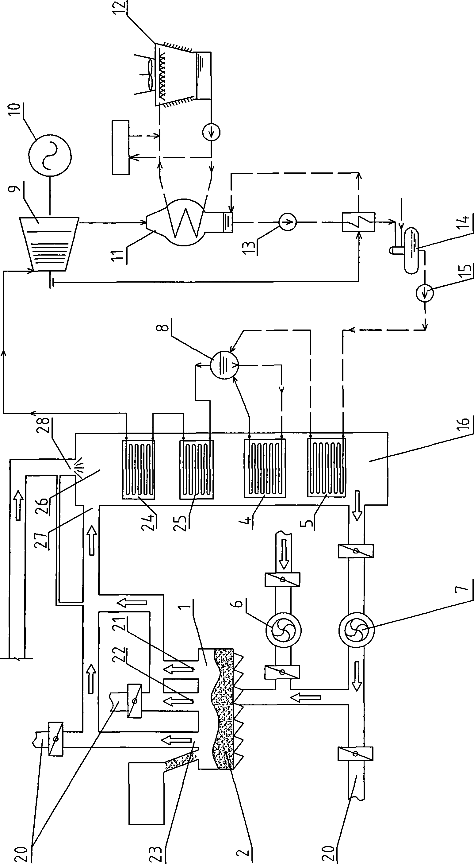
[0013] The structure of this embodiment is as figure 2 As shown, the sintering waste heat power generation system with by-product gas supplementary combustion includes cooler 1, waste heat boiler 16, steam drum 8, steam turbine 9, generator 10, condenser 11, cooling tower 12, condensate water pump 13, oxygen removal 14 and boiler feed water pump 15, the cooler 1 is provided with three exhaust gas outlets, namely the high-temperature exhaust gas outlet 23 located in the high-temperature area, the medium-temperature exhaust gas outlet 22 located in the medium-temperature area, and the low-temperature exhaust gas outlet 21 located in the low-temperature area, and the waste heat boiler 16 Inside from top to bottom, there are a combustion furnace 26, a high-temperature superheater 24, a low-temperature superheater 25, an evaporator 4 and an economizer 5. The combustion furnace 26 of the waste heat boiler 16 is provided with a high-temperature exhaust gas outlet 23, a medium-tempera...

Embodiment 2

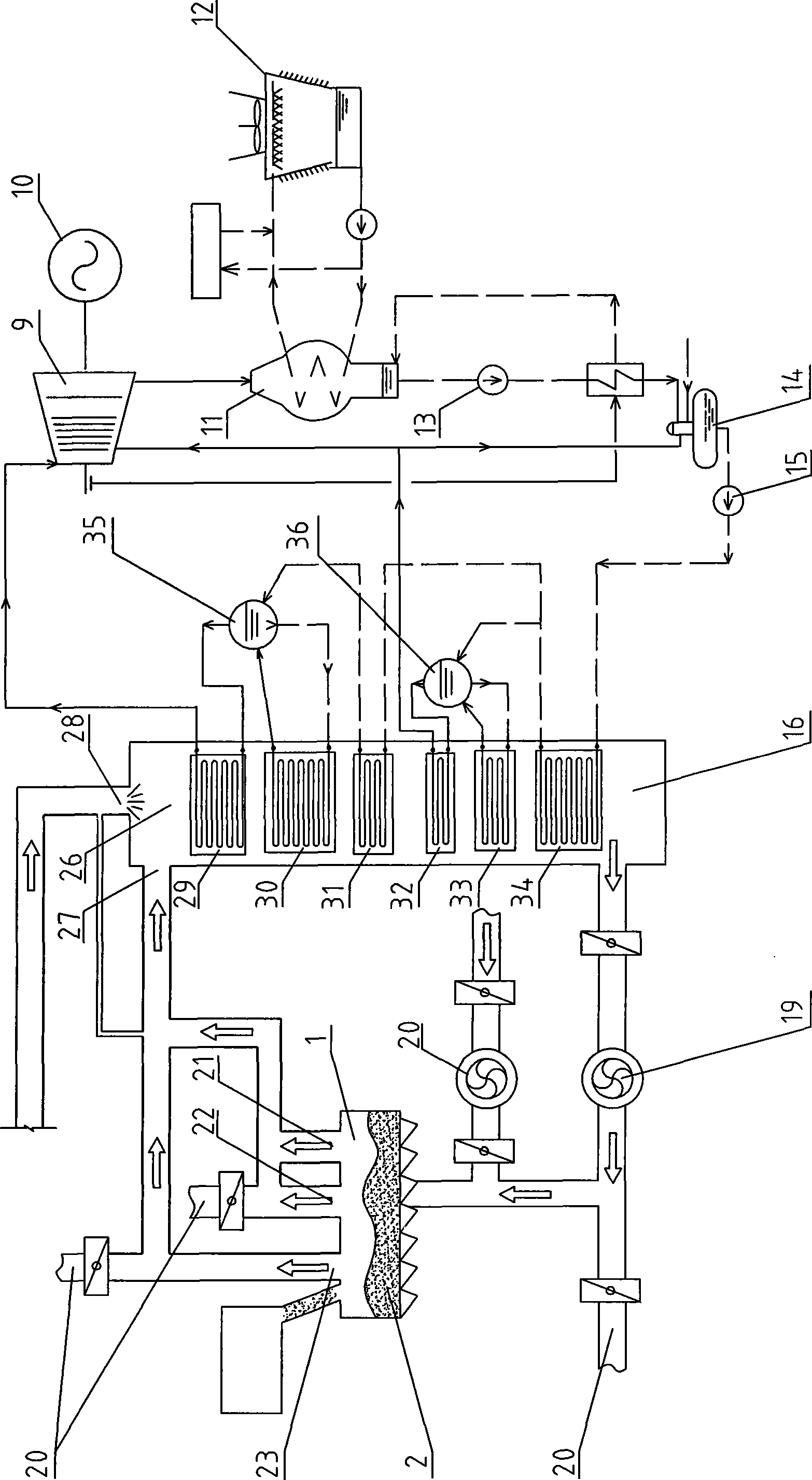
[0019] The structure of this embodiment is as image 3 As shown, the difference from Embodiment 1 is that the waste heat boiler 16 is sequentially provided with a combustion furnace 26, a high-pressure superheater 29, a high-pressure evaporator 30, a high-temperature economizer 31, a low-pressure superheater 32, and a low-pressure evaporator. 33 and a low temperature economizer 34, the steam drum is divided into a high pressure drum 35 and a low pressure drum 36, the boiler feed pump 15 is connected to the inlet of the low temperature economizer 34, the outlet of the low temperature economizer 34 is connected to the high temperature economizer 31 The inlet is connected to the water inlet of the low-pressure steam drum 36, the water inlet of the low-pressure evaporator 33 is connected to the water outlet of the low-pressure steam drum 36, the outlet of the low-pressure evaporator 33 is connected to the vapor-liquid two-phase inlet of the low-pressure steam drum 36, and the low-p...


PUM


Abstract

The invention relates to a residual heat power generation system which is a power generation system with by-product gas supplemental combustion by sintering residual heat. The power generation system comprises a cooling machine, a waste heat boiler, a steam drum, a steam turbine, a boiler feed pump, an induced draft fan, an air blower and a chimney. A combustion hearth, a high-temperature superheater, a low-temperature superheater, an evaporator and an economizer are sequentially arranged on the waste heat boiler from top to bottom; the outlet of the high-temperature superheater and the steam inlet of the steam turbine are connected with each other by a pipeline; the waste heat boiler is provided with a sintering waste gas inlet and a by-product gas inlet; and the upper part of the cooling machine is provided with a high-temperature waste gas outlet, a middle-temperature waste gas outlet and a low-temperature waste gas outlet. The residual heat power generation system can greatly increase the temperature of the smoke and the temperature and the pressure of the overheated steam at the inlet of the steam turbine, and can improve the power generation capability.

Description

technical field [0001] The invention relates to a waste heat power generation system, in particular to a sintering waste heat power generation system with supplemental combustion of by-product gas. Background technique [0002] Existing sinter waste heat power generation systems such as figure 1 As shown, it includes a cooling machine 1, a waste heat boiler 16, a boiler feed water pump 15, a deaerator 14, a steam turbine 9, a generator 10, a condenser 11, a cooling tower 12 and a steam drum 8. There are ores 2 in the cooling machine 1, The cooler 1 is provided with a high-temperature air outlet 17 and a low-temperature air outlet 18 , and the waste heat boiler 16 is provided with a superheater 3 , an evaporator 4 and an economizer 5 sequentially from top to bottom. Waste heat boiler 16 imports waste gas from two air outlets 17 and 18 in cooler 1, and the inlet temperature is about 350-400°C. The waste gas enters waste heat boiler 16 after passing through dust collector 19, ...

Claims


Application Information

Patent Timeline
IPC IPC(8): F27D17/00F01K11/02F01K27/02
CPCY02P10/25
Inventor 尧志潘亚林王可黄健文莫蓝彬徐立海顾昊
Owner 江苏东能环保能源科技有限公司
Why Eureka
Try Eureka