
Cooling method for gain medium in solid laser and low interior heat solid laser

A solid-state laser, gain medium technology, used in lasers, laser parts, phonon exciters, etc.

Inactive Publication Date: 2009-08-12
谭吉春
View PDF2 Cites 11 Cited by
  • Summary
  • Abstract
  • Description
  • Claims
  • Application Information

AI Technical Summary

Problems solved by technology

In existing laser coolers, there is no method to use dual pump beams to excite superradiation and remove waste heat directly from inside the gain medium

Method used


Image

  • Cooling method for gain medium in solid laser and low interior heat solid laser
  • Cooling method for gain medium in solid laser and low interior heat solid laser
  • Cooling method for gain medium in solid laser and low interior heat solid laser

Examples


Embodiment 1

[0020] Example 1: Side-pumped chip low internal heat laser

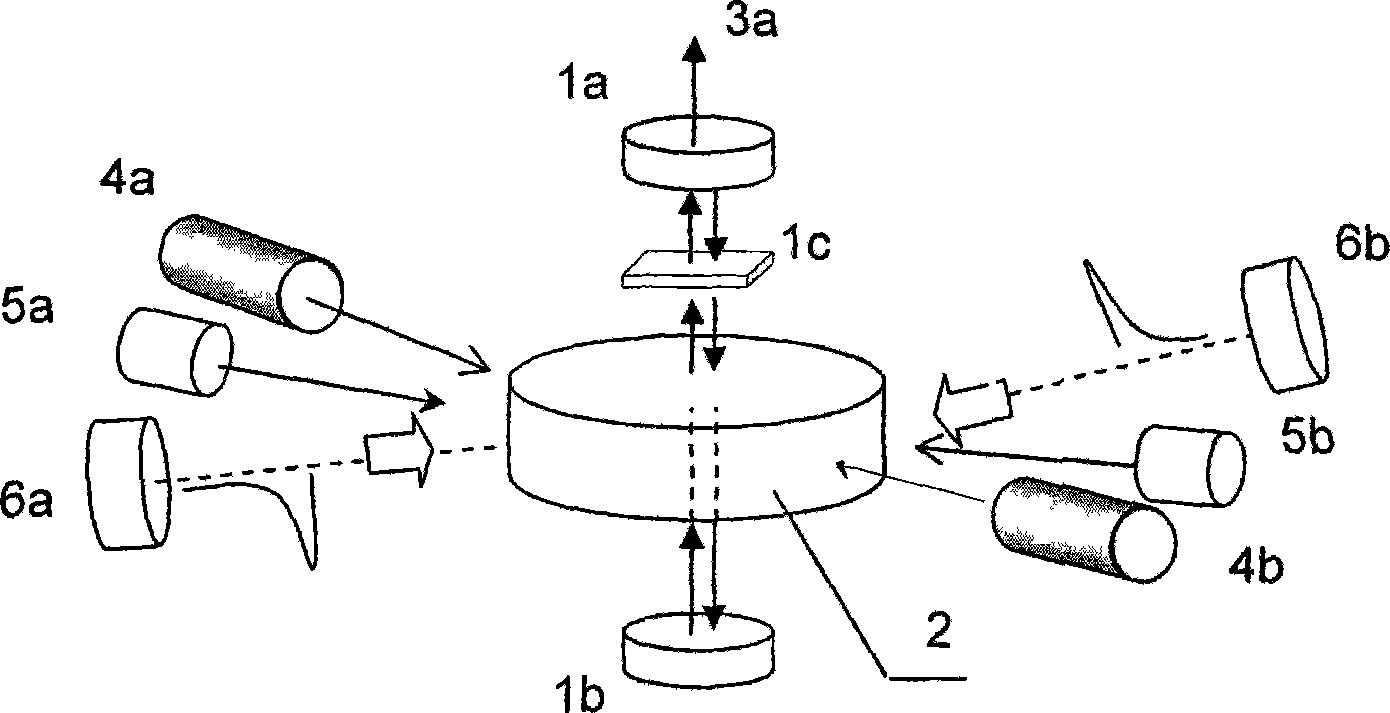
[0021] control figure 1 : In a chip laser, a laser oscillating part and a laser cooling part are combined into one. The laser oscillating components include: gain medium 2, pump light sources 4a and 4b that generate population inversion, laser output mirror 1a, total reflection mirror 1b, and near-infrared laser output beam 3a. The laser cooling components include: cooling medium, main pumping light sources 5a, 5b, and auxiliary pumping (pulse) light sources 6a, 6b. The cooling medium of the laser cooling component is the gain medium 2, that is, the laser gain medium also serves as the laser cooling medium, and its doping method is divided into two basic types: single-component doping and dual-component doping.

[0022] 1. Laser gain medium doubles as cooling medium

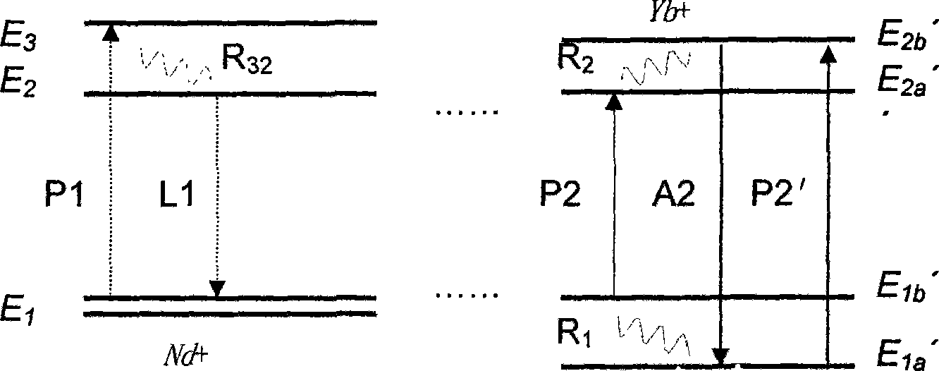
[0023] The single-component doped gain medium is Yb 3+ : KGd(WO 4 ) 2 Crystal (hereinafter referred to as Yb 3+ : KGW), the typical value of ytt...

Embodiment 2

[0035] Example 2: Side-pumped bar-shaped laser with low internal heat

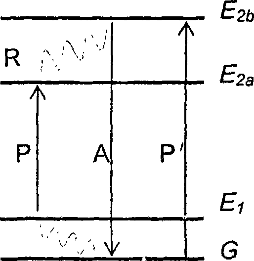
[0036] control Figure 4 : The bar laser is composed of laser oscillation and laser cooling. Laser oscillation components include: Yb or Nd-doped gain medium 2, pump light sources 4a, 4b that generate population inversion and resonant cavity (laser output mirror 1a, total reflection mirror 1b). The near-infrared laser output beam is shown in Figure 3. The laser cooling components include: cooling medium. Main pump light sources 5a, 5b, auxiliary pump (pulse) light sources 6a, 6b. The laser-cooled pump light source 5a, 5b pumps the medium 2 from the side, and the optical path is as follows: Figure 4 shown. The pump light source 5a, 5b cooperates with the light source 6a, 6b to induce superradiation and improve the cooling efficiency, such as figure 2 shown. Auxiliary pump beams (pulses) 6a, 6b for inducing superradiation are incident into the medium 2 from the side, so as to induce superradiation a...


PUM


Abstract

The invention discloses a method for cooling a gain medium in a solid laser and a solid laser having lower internal heat. A laser pump light source and a refrigerating pump light source which can adjust light intensity, pulse width and repetition rate respectively are arranged. The gain medium corresponding to the laser pump light source and a refrigerating medium corresponding to the refrigerating pump light source are the same block of crystal mixed with rare earth ions. Two physical processes of laser refrigeration and laser oscillation are controlled to alternatively or synchronously operate by a sequence signal circuit and a gain switch so as to approximately counteract the refrigerating capacity of superradiance on the media and the heat generated by the laser oscillation, to make the laser in a laser resonance cavity transmitted along the crystal 'apyrexia' direction, and to reduce the thermal lens effect caused by a residual temperature gradient in the crystal . The method converts waste heat in the gain medium into an anti-Stocks scattering photon which has fast radiation and small residual temperature gradient. A main pump light beam and an auxiliary pump light beam (pulse) are used for inducing the crystal to emit the superradiance. The refrigerating efficiency of the superradiance is better than that of fluorescence in the prior laser refrigerators.

Description

technical field [0001] The invention relates to a cooling method for a gain medium in a solid laser and a low internal heat solid laser. Background technique [0002] In existing solid-state lasers, the problem that the thermal effect of the gain medium (especially the thermal lens effect) affects the quality of the output beam is one of the technical difficulties preventing the laser from increasing the output power level. 200710188442.3 discloses a cooling method of a crystal heat pipe heat sink in a diode-pumped solid-state laser. The heat pipe is composed of a liquid working fluid, a tube shell and a tube core. The liquid working fluid conducts the high-density waste heat in the laser crystal to the cold source. 200610119575.0 discloses a cooling structure for solid-state thin-film lasers. The laser is composed of multiple modules, each of which consists of two gain medium sheets placed in parallel, and two diamond heat sinks are respectively attached to the sides of t...

Claims


Application Information

Patent Timeline
Patent Type & Authority Applications(China)
IPC IPC(8): H01S3/042H01S3/0941H01S3/16
Inventor 谭吉春
Owner 谭吉春
Learn More