
Optical bicomponent antiglossing pigment and preparation thereof

A matting coating, two-component technology, applied in the direction of epoxy resin coatings, coatings, etc., can solve the problems of insufficient adhesion of one component, poor aging resistance of three components, poor matting performance, etc.

Inactive Publication Date: 2011-11-09
云南光电辅料有限公司
View PDF0 Cites 1 Cited by
  • Summary
  • Abstract
  • Description
  • Claims
  • Application Information

AI Technical Summary

Problems solved by technology

[0008] The purpose of the present invention is to solve the disadvantages of the existing optical matting coatings, such as poor matting performance, insufficient single-component adhesion, and poor aging resistance of the three-component epoxy system, and provide a kind of coating with strong matting ability, room temperature curing, Good adhesion, anti-aging two-component optical matting coating and preparation method thereof

Method used


Image

  • Optical bicomponent antiglossing pigment and preparation thereof
  • Optical bicomponent antiglossing pigment and preparation thereof
  • Optical bicomponent antiglossing pigment and preparation thereof

Examples


Embodiment 1

[0025] Embodiment 1 (weight ratio)

[0026] Component A formula:

[0027]

[0028] Component B formula:

[0029] Polyamide 651 60 DB-602 Silane coupling agent 3

[0030] Ancamine 1561 20 n-Butanol 17

[0031] When preparing, first add NPPR-133LEPU, D.E.N 431, FW200, carbon nanotubes, Disperbyk-103 dispersant, 1 / 2 toluene, 1 / 2 n-butanol to a sand mill and grind for 3 hours. Take out the ground color paste and put it into a high-speed disperser, add the remaining materials of component A under high-speed stirring, disperse and mix evenly, filter, discharge, sub-package, and use it as component A for later use; polyamide 651, Ancamine 1561 , DB-602, and n-butanol are placed in the reactor and stirred evenly, and used as component B for later use. When in use, mix evenly according to A:B=3:1 (weight ratio) and then brush it on the burr of the optical element. It will be cured after 24 hours at room temperature or 2 hours at 80°C. The visible light reflectance is ≤3%, and th...

Embodiment 2

[0032] Embodiment 2 (weight ratio)

[0033] Component A formula:

[0034]

[0035] Component B formula:

[0036] 593 epoxy curing agent 85 absolute alcohol 3

[0037] DB-602 silane coupling agent 5 ethyl acetate 7

[0038] When preparing, first add SL-102C, F-48, special 6# carbon black, carbon nanotubes, Disperbyk-103 dispersant, 1 / 2 xylene, 1 / 2 n-butanol to a sand mill and grind for 3 hours . Take out the ground color paste and put it into a high-speed disperser, add other materials remaining in component A under high-speed stirring, disperse and mix evenly, filter, discharge, pack, and use it as component A for later use; mix 593 epoxy curing agent, Put DB-602 silane coupling agent, absolute ethanol, and ethyl acetate in a reaction kettle and stir to mix evenly, and use it as component B for later use. When in use, mix evenly according to A:B=3:1 (weight ratio) and then brush it on the burr of the optical element. After curing for 24 hours at room temperature or 2 h...


PUM

PropertyMeasurementUnit
reflectanceaaaaaaaaaa

Abstract

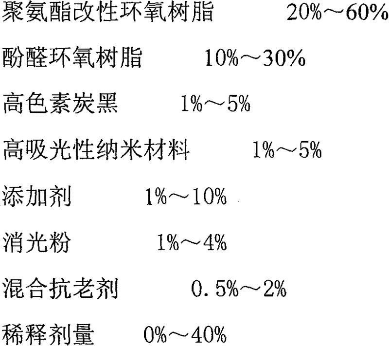
The invention discloses a novel optical two-component extinction coating and a method for preparing the same. The novel optical two-component extinction coating is prepared from component A and component B; the component A comprises 20-60 percent of polyurethane-modified epoxy resin, 10-30 percent of novolac epoxy resin, 1-5 percent of high-pigment carbon black, 1-5 percent of highly light absorbing nanometer material, 1-10 percent of additive, 1-4 percent of extinction powder, 0.5-2 percent of mixed antiager and 0-40 percent of diluent; and the component B comprises 70-90 percent of epoxy hardener, 0-3 percent of silane coupling agent and 10-30 percent of diluent. The novel optical two-component extinction coating has good extinction effect, strong adhesive force and good weather resistance, is especially used for the extinction of optical elements used for a precision photoelectric instrument with higher parasitic light requirement and can also be used for the extinction of the surfaces of a lens barrel, a lens hood, a diaphragm, a light blocking ring of the precision photoelectric instrument and other system.

Description

1. Technical field [0001] The invention relates to a matting coating, in particular to a two-component matting coating for optics and a preparation method thereof. 2. Background technology [0002] Stray radiation, also known as stray light or stray light, refers to the radiant energy of other non-imaging (or non-target) rays that diffuse on the surface of the imaging (or detector) in addition to the imaging (or target) light in the optical system. And the radiant energy of the target light that reaches the imaging (or detector) through the abnormal optical path. For the imaging optical system, stray light reduces the discrimination of the lens, which makes the image blurred and even produces phantoms; if the stray light rate of different wavelengths is greatly different, it will lead to image color distortion; In the optical system, stray light is easy to form multiple ghost images, and the light energy near the ghost images is concentrated, which will cause permanent dama...

Claims


Application Information

Patent Timeline
Patent Type & Authority Patents(China)
IPC IPC(8): C09D163/00C09D163/04C09D7/12C09D5/00
Inventor 句红兵李妹明
Owner 云南光电辅料有限公司
Learn More