
Dedusting and dehumidifying method for air with freezing method and equipment thereof

A technology of gas dust removal and freezing method, applied in gas dust removal, condensed non-gaseous material gas purification, separation methods, etc., can solve problems such as affecting human health, increasing dust concentration, hidden safety hazards, etc., saving energy consumption and reducing relative humidity. , the effect of reducing emissions

Inactive Publication Date: 2009-07-15
无锡金龙石化冶金设备制造有限公司 +1
View PDF0 Cites 10 Cited by
  • Summary
  • Abstract
  • Description
  • Claims
  • Application Information

AI Technical Summary

Problems solved by technology

The traditional method is to use wet dust removal (annular seam washing system, double venturi washing system, etc.), and use atomized water droplets to capture dust particles in the gas. After wet dust removal, the humidity and dust content of the clean gas will drop significantly. For example, the temperature of the net converter gas is about 70°C, and the dust content is 70-200mg / Nm 3 , the relative humidity is 100%, such gas is directly discharged into the atmosphere or discharged into the atmosphere after being burned, and the dust contained in it will form respirable dust, which will increase the concentration of respirable dust in the atmosphere, causing air pollution and affecting the human body health
In addition, due to the high relative humidity of the gas after wet dedusting, a large amount of condensed water will be generated during pipeline transportation, which will corrode the pipeline and cause safety hazards

Method used


Image

  • Dedusting and dehumidifying method for air with freezing method and equipment thereof
  • Dedusting and dehumidifying method for air with freezing method and equipment thereof
  • Dedusting and dehumidifying method for air with freezing method and equipment thereof

Examples


Embodiment Construction

[0023] The specific implementation manners of the present invention will be further described in detail below in conjunction with the accompanying drawings.

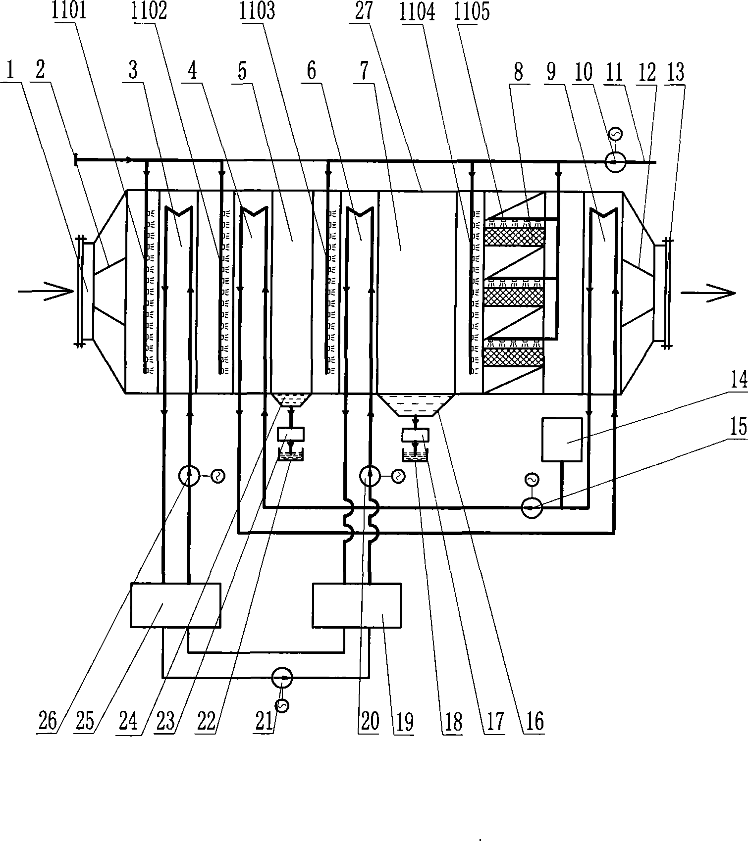
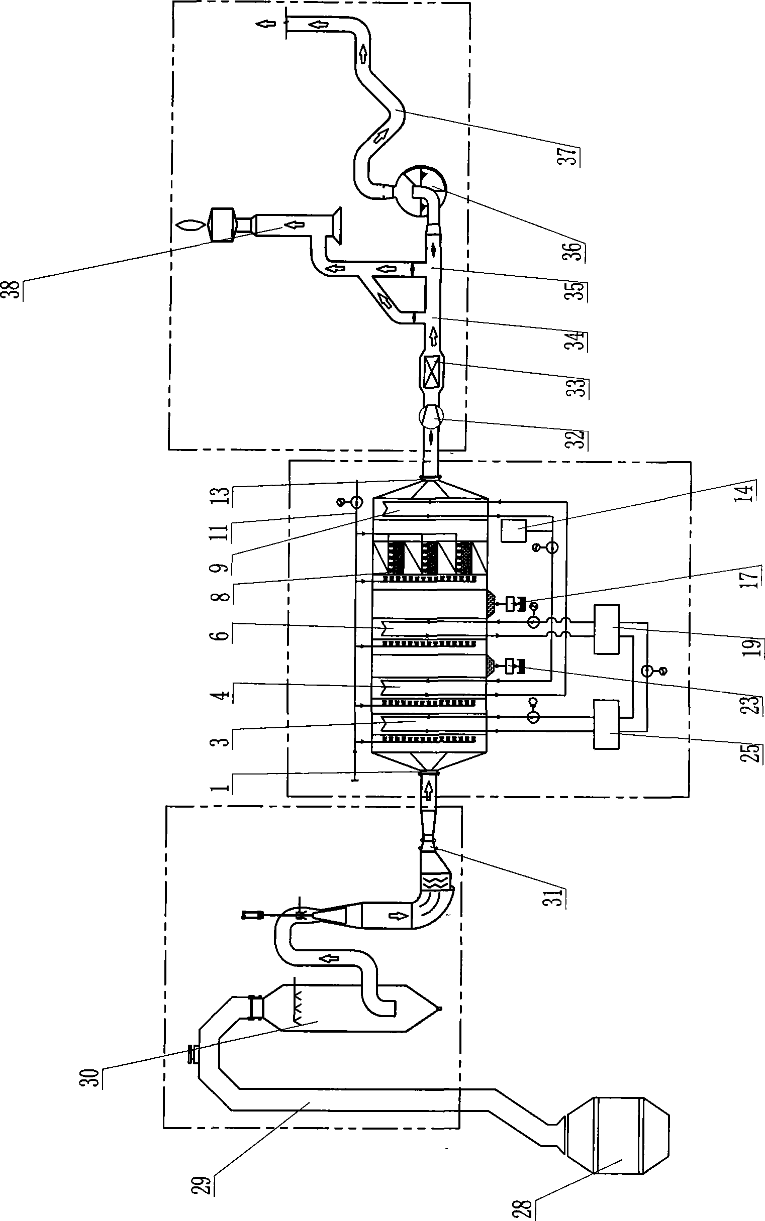
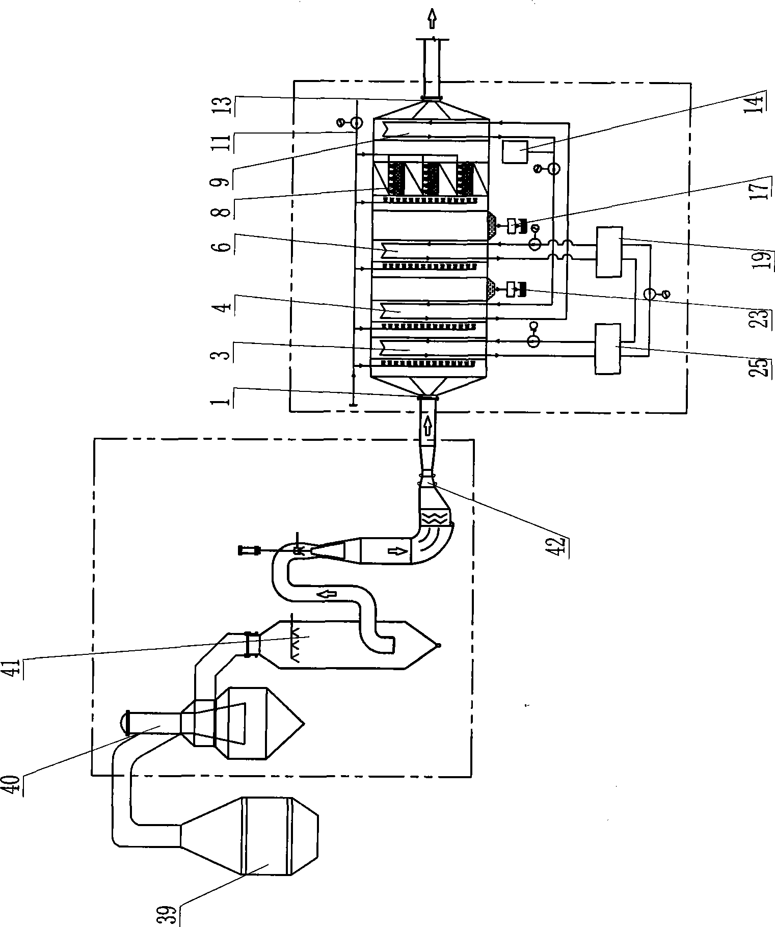
[0024] like figure 1 As shown, the present invention includes a housing 27, the two ends of the housing 27 are provided with a gas inlet 1 and a gas outlet 13, and the gas inlet 1 and the gas outlet 13 are respectively connected to the gas delivery pipeline. Inlet deflector 2, pre-cooler 3, self-circulating cooler 4, first drainage section 5, cooler 6, second drainage section 7, demister 8, reheating heater 9 and outlet deflector 12 sequence The device is installed in the housing 27 between the gas inlet 1 and the gas outlet 13. The above-mentioned precooler 3, self-circulating cooler 4, cooler 6 and reheating heater 9 can all use bare tube or finned tube heat exchangers Structure, precooler 3 is connected with cooling equipment 25 through pipeline and water pump 26, and cooling equipment 25 is the cooling tower or othe...


PUM


Abstract

The invention relates to a dedusting and dehumidifying method and equipment thereof for furnace top coal gas of a blast furnace, a converter or a COREX furnace. The method comprises the steps of precooling, self-circulation cooling, re-cooling, demisting and self-circulation heating and rewarming. The equipment comprises a stream guide plate, a precooler, a self-circulation cooler, a first water discharge section, a cooler, a second water discharge section, a demister, a rewarming heater and an outlet stream guide plate which are sequentially arranged between a gas inlet and a gas outlet in a shell. The method and the equipment are used to reduce the emission of dust and the pollution to the air. The heat of gas at the inlet and the cold output of gas at the outlet are recycled so as to repeatedly utilize energy sources and save the energy source consumption; the relative humidity of coal gas treated by the method and the equipment is reduced, thereby the occurrence of condensed water in the process of pipeline conveying is reduced, the corrosion action to the pipeline is reduced and the safety is improved; in addition, the reduction of the relative humidity of the coal gas improves the thermal value of the coal gas.

Description

technical field [0001] The present invention relates to a dust-removing and dehumidifying method and equipment for gas containing dust and moisture, in particular to a method and equipment for dedusting and dehumidifying gas at the top of a smelting blast furnace, converter or COREX furnace. Background technique [0002] Blast furnaces, converters or COREX furnaces used for ironmaking or steelmaking will produce a large amount of gas during smelting. Converter gas (LDG), blast furnace gas (BFG) and Corex furnace gas (CrG) contain reusable combustible gases ——In addition to gas, it also contains a large amount of water vapor and dust, and the dust content and moisture content are relatively high. If it is to be recycled, it needs to be dedusted and dehumidified. The traditional method is to use wet dust removal (annular seam washing system, double venturi washing system, etc.), and use atomized water droplets to capture dust particles in the gas. After wet dust removal, the h...

Claims


Application Information

Patent Timeline
IPC IPC(8): B01D53/26B01D49/00B01D5/00C10K1/02C10K1/04
Inventor 张宜万漆林宝边玉婷
Owner 无锡金龙石化冶金设备制造有限公司
Learn More