
Multi-level depressurization collector for traveling wave tube

A technology of traveling wave tubes and collectors, which is applied in the field of multi-stage step-down collectors, can solve the problems of poor adaptability of insulating materials, hindering the application of traveling wave tubes, and increasing the volume of collectors, and achieves light weight, easy processing and assembly. The effect of simple process and small volume

Inactive Publication Date: 2009-06-03
UNIV OF ELECTRONIC SCI & TECH OF CHINA
View PDF0 Cites 13 Cited by
  • Summary
  • Abstract
  • Description
  • Claims
  • Application Information

AI Technical Summary

Problems solved by technology

In order to adapt to the lead-out method of this kind of electrode power line, the insulator needs to be a ceramic insulator with a certain strength, and the ceramic insulating part and the corresponding section of the shell must be made into separate parts for each pole, and then assembled into a whole when assembling, so The entire set of insulators and their shells are not only complex in shape, but also poor in processing technology, difficult to assemble, and poor in adaptability to insulating materials; at the same time, the power line lead-out tube hole needs to be set in the insulating layer, which will also increase the volume of the collector and hinder Traveling wave tubes are used in areas with volume and weight restrictions, such as space and other fields; attached Figure 4 It is a schematic diagram of the structure of the multi-stage step-down collector disclosed in "Traveling wave tube using small multi-stage step-down collector" (NASA Technical Paper, 1987)

Method used


Image

  • Multi-level depressurization collector for traveling wave tube
  • Multi-level depressurization collector for traveling wave tube
  • Multi-level depressurization collector for traveling wave tube

Examples


Embodiment 1

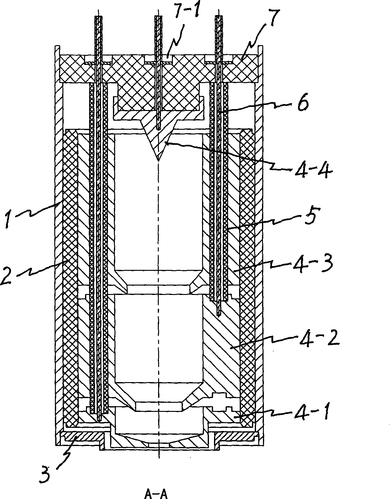
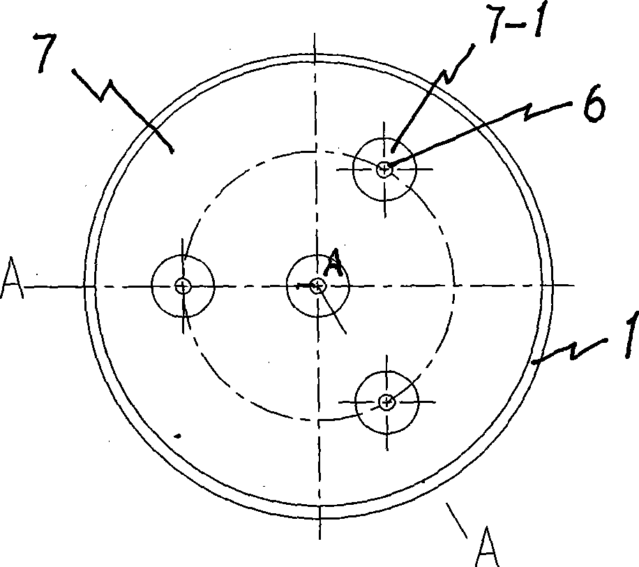
[0012] Embodiment 1: Taking the 4-stage step-down collector pole for a traveling wave tube as an example, the inner and outer diameters of the collector shell 1 are φ42mm and φ45mm respectively, and the length is 90mm; the insulating cylinder 2, the insulating back cover 7 and the insulating conduit 5 are all Using conventional ceramic insulators, the inner and outer diameters of the insulating cylinder 2 are φ36mm and φ42mm respectively, the axial length is 65mm, the outer diameter of the insulating back cover 7 is φ43mm, the total thickness is 12mm, and the center hole of the power line lead-out hole 7-1 is located at the axis , The remaining 3 holes are set according to the distance of 120° and the radius R13.5mm. The electrode holder 7-2 has a diameter of φ18mm and a height of 6mm; the outer diameter of the insulating conduit 5 is φ5mm and the tube wall thickness is 2mm; the first-level electrodes 4-1, 4-2, 4-3 main bodies have an inner diameter of φ19mm, an outer diameter ...

Embodiment 2

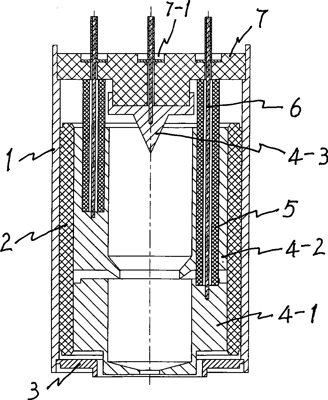
[0013] Embodiment 2; image 3 It is a schematic diagram of the structure of the 3-stage step-down collector of this embodiment; the inner and outer diameters of the collector shell 1 and the insulating cylinder 2 are the same as those of the embodiment 1, and the axial lengths are 76mm and 51mm respectively, and the insulating cylinder 2 is used in this embodiment. Beryllium oxide (BeO) ceramics; the second level electrode 4-2 and the third level electrode 4-3 are respectively the same as the third level electrode 4-3 and the fourth level electrode 4-4 in embodiment 1, and the first level electrode 4-1 The inner diameter of the main body is φ19mm, the outer diameter is also φ36mm, and the axial length is 20mm; the outer diameter and wall thickness of the front cover 3, the insulating conduit 5, the outer diameter and total thickness of the insulating back cover 7, and the middle electrode seat 7 The diameter of -2 is also all identical with embodiment 1, and 3 power line lead-...


PUM


Abstract

This invention belongs to a multi-level depressurization collector matched with traveling wave tube, comprising a cylindrical shell, each electrode and power source leading wire thereof mounted in the shell, an insulator mounted between each electrode and shell, an insulator rear cover provided with a power source leading hole, a front end cover. Because the original spare-parts type shell and the insulator thereof are designed to the integral cylindrical body with simple structure, the last level electrode is mounted at the central position of the inner wall of the rear cover, and the other each rear end electrodes are provided with the power source leading hole provided with an insulated sleeve for the front end electrode power source leading hole, this invention is featured with simple and compact structure, simple processing and assembling, strong suitability to the insulated material, small size, light weight and wider application range and so on, such that the defaults of complicated shapes the original spare-parts type shell and the insulator thereof has, need of mounting power source leading hole in the insulated layer, bad processing technology, difficult of assembling and bad suitability to the insulated material which are existed in the background technology are conquered.

Description

technical field [0001] The invention belongs to an electric vacuum device in microwave technology, in particular to a multi-stage step-down collector used in conjunction with a traveling wave tube. Background technique [0002] The multi-stage step-down collector is used in conjunction with the traveling wave tube, including the collector shell, the electrodes of all levels ring-shaped in the shell and the corresponding power lead-out wires, the ceramic insulator between the electrodes and the shell, and the The power cord lead-out (pipe) hole in the insulator, and the insulator rear cover located at the rear of the casing with a power cord lead-out hole. This kind of multi-stage step-down collector is to classify and collect electrons after high-frequency action according to speed, so that electrons with high kinetic energy hit low potential electrodes, and electrons with low kinetic energy hit high potential electrodes, thus When the electrons reach the corresponding elec...

Claims


Application Information

Patent Timeline
IPC IPC(8): H01J23/027H01J25/34
Inventor 宫玉彬黄勇飞岳玲娜魏彦玉王文祥
Owner UNIV OF ELECTRONIC SCI & TECH OF CHINA
Learn More