
Stone sawing machine

A stone sawing machine and saw blade technology, which is applied to stone processing tools, stone processing equipment, manufacturing tools, etc., can solve the problems of stable stone storage, waste of raw materials, and easy cracking of stone flakes, so as to improve work efficiency and reduce production costs , good cutting stability

Inactive Publication Date: 2009-05-13
陈少波
View PDF0 Cites 11 Cited by
  • Summary
  • Abstract
  • Description
  • Claims
  • Application Information

AI Technical Summary

Problems solved by technology

It can't solve the problem of cutting slices with a width of more than 800mm, and the huge vibration causes the processed stone flakes to be easily broken due to great impact, and it cannot cut ultra-thin stone flakes
[0004] 2. The disc machine relies on the rigidity of the bottom to cut the stone, and the trajectory of the cutting line deviates greatly, resulting in uneven thickness of the product
[0005] 3. The bottom of the disc saw is very huge, and it is impossible to process stone chips other than flat surfaces.
[0006] 4. High energy consumption, the strong vibration generated during the cutting process of the circular saw leads to a lot of energy waste
[0007] 5. The waste of raw materials is serious, and the circular saw can only cut products with large thickness; the width of the cutting line is too large, which leads to serious waste of raw materials
[0008] The band saw used in processing wood has many advantages over the circular saw also used for processing wood, but because the strength of stone is much greater than that of wood and its toughness is lower than that of the base material, even if the band saw with a diamond saw blade is used to cut stone. Some problems, such as: the vibration of the saw blade, the stability of the stone, etc.

Method used


Image

  • Stone sawing machine
  • Stone sawing machine
  • Stone sawing machine

Examples


Embodiment Construction

[0019] In order to further illustrate the stone sawing machine of the present invention, a more detailed description will be given below in conjunction with the examples.

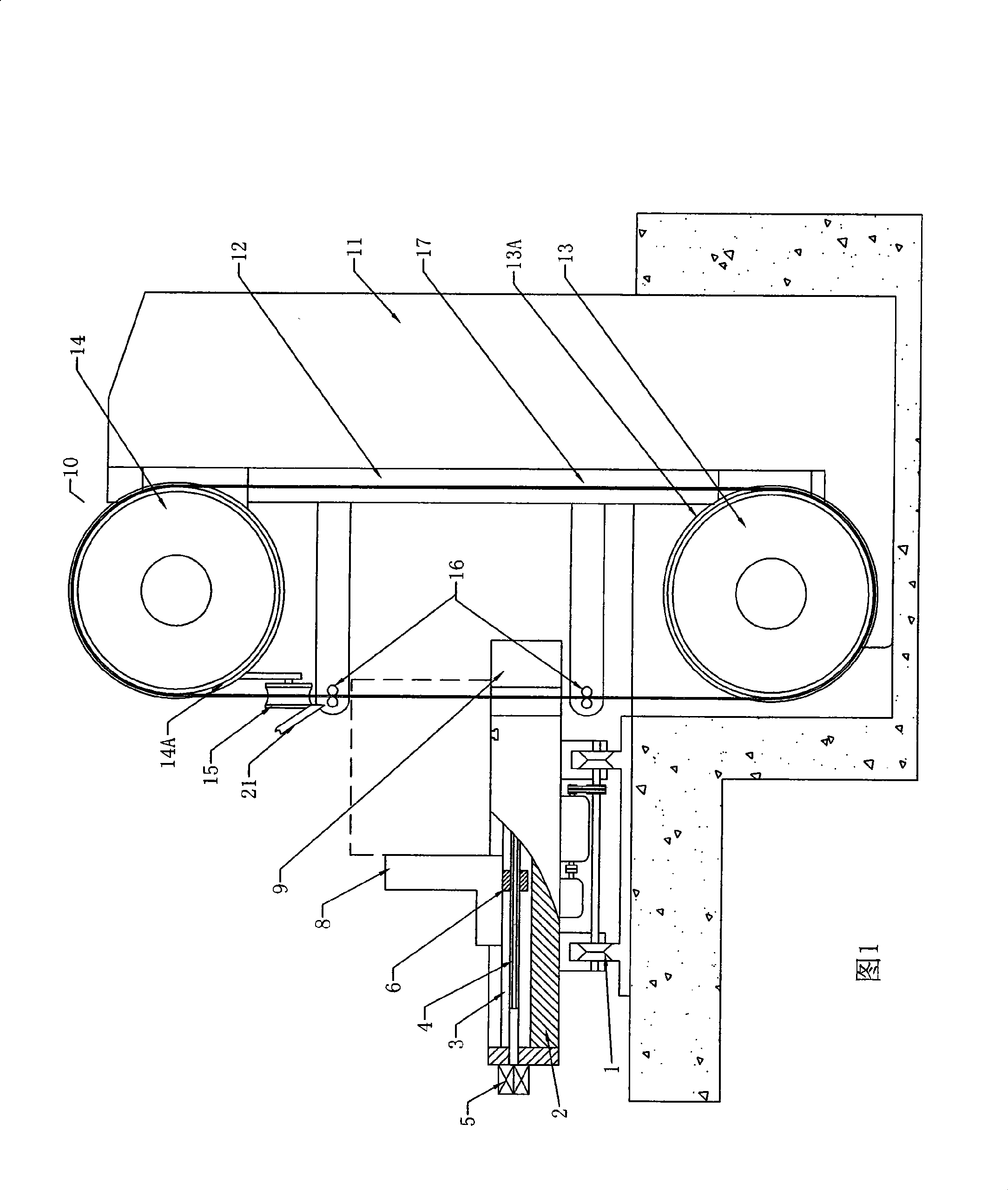
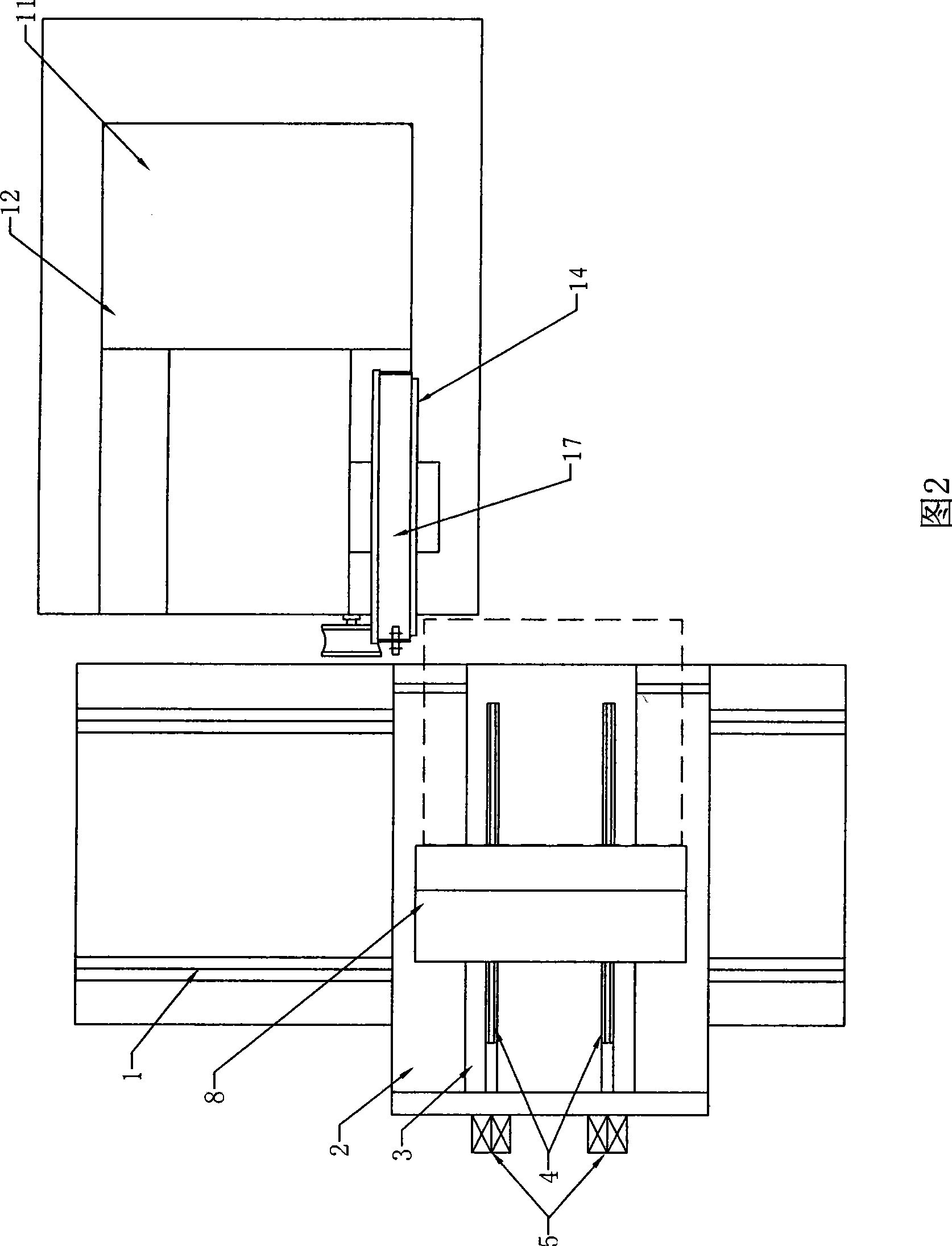
[0020] Fig. 1 is a schematic diagram of the stone sawing machine of the present invention, from which it can be seen that the stone sawing machine of the present invention is mainly composed of a cutting part 10 and a feeding part, wherein the cutting part 10 includes a fixed frame 11, a movable frame 12, and is mounted on a fixed frame. The driving wheel 13 on the frame 11 and the driven wheel 14 installed on the movable frame 12 are composed of the fixed frame 11 directly fixed on the ground. Since the stone is relatively heavy, in order to reduce the lifting of the stone during processing, in fact, usually The fixed frame 11 is placed in a pit on the ground.

[0021] Between the movable frame 12 and the fixed frame 11, the distance therebetween can be adjusted by a jacking device. Tension hangs on the s...


PUM


Abstract

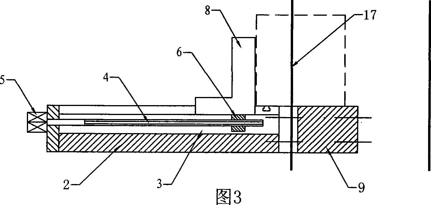
A stone sawing machine comprises a fixed frame, a movable frame, a driving wheel, a driven wheel, a ring-shaped saw blade, a orbit, a workbench and a mobile push pressure plate, wherein, lugs are formed on one side of the driving wheel and one side of the driven wheel; holding devices which clamp a downward moving saw blade are arranged on the upper surface and the lower surface of the workbench and a stone respectively; an auxiliary table board is arranged outside the working end of the workbench; the mobile push pressure plate is pushed by a transverse pushing device which comprises a lead screw, a driving device and a slide block; a cooling device is arranged on the machined surface of the stone; the saw blade comprises a saw body, rectangular teeth and blades; the rectangular teeth are formed on one side of the saw body; and two blades are welded on the two sides of the saw body. The stone sawing machine has the advantages that the difficult problem for cutting ultra-wide hard stone flakes is solved; the difficult problem for cutting ultrathin stone flakes is solved; the difficult problem of non-uniform thickness cutting is solved; the difficult problem for curved surface cutting is solved; the manufacturing cost is reduced; and manpower can be reduced, and the work efficiency can be improved by adopting the controlling of an automatic control system.

Description

technical field [0001] The invention relates to a stone processing mechanical equipment, in particular to a stone saw machine using a band saw. Background technique [0002] At present, a circular saw stone sawing machine is generally used for cutting stones. This kind of stone sawing machine has the following disadvantages: [0003] 1. The width of cutting stone depends on the radius of the circular saw. Since the cutting movement will generate strong vibration, the radius of the circular saw generally does not exceed 1000 mm. It cannot solve the difficult problem of cutting when the width exceeds 800 mm, and the huge vibration causes the processed stone flakes to be easily broken due to the great impact, and the ultra-thin stone flakes cannot be cut. [0004] 2. The disc machine relies on the rigidity of the bottom to cut the stone, and the trajectory of the cutting line deviates greatly, resulting in uneven thickness of the product. [0005] 3. The bottom of the circula...

Claims


Application Information

Patent Timeline
IPC IPC(8): B28D1/08
Inventor 陈少波
Owner 陈少波
Learn More