
Pressure die-drawing device for producing bimetallic wire

A drawing die and bimetal technology, applied in wire drawing die and other directions, can solve the problems of inability to produce high-quality bimetal composite wire, low adhesion between lubricating material and wire billet surface, uneven stress distribution on wire surface, etc. Reduced coefficient of friction, no scratches on the surface, and reduced pull-out force

Inactive Publication Date: 2009-05-06
王玉凯 +3
View PDF7 Cites 6 Cited by
  • Summary
  • Abstract
  • Description
  • Claims
  • Application Information

AI Technical Summary

Problems solved by technology

This existing drawing device has the following disadvantages: 1. The adhesion between the lubricating material and the wire blank surface is small, and the friction force between the drawing die and the wire blank is large. Find a balance between the drawing force and the drawing force - a suitable drawing angle of the drawing die; 2. The drawing die and the wire blank are not cooled well during the drawing process, and the temperature is not balanced
This affects the metallurgical combination of copper and aluminum or copper and steel, and cannot produce high-quality bimetallic composite wires such as copper-clad aluminum or copper-clad steel; and causes scratches on the surface of the bimetallic wire, and the surface stress of the wire after drawing The distribution is uneven, and it is impossible to produce fine wires below 0.1mm

Method used


Image

  • Pressure die-drawing device for producing bimetallic wire

Examples


Embodiment Construction

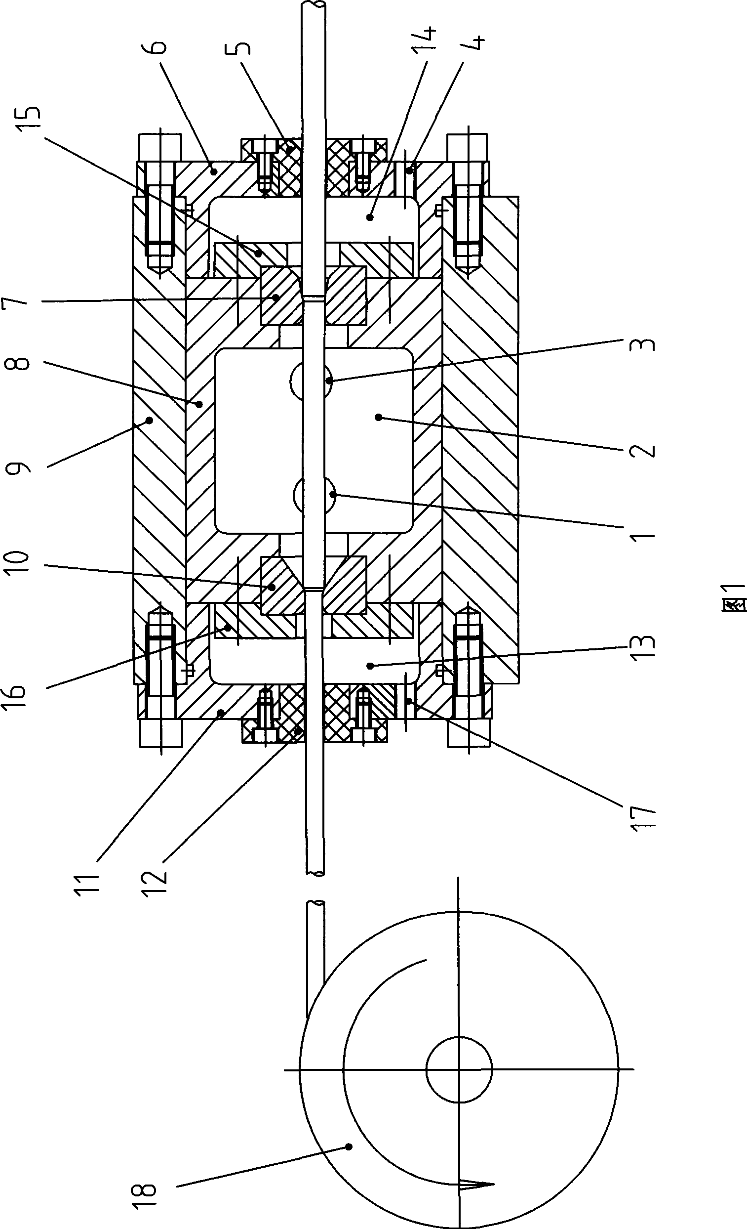
[0013] As shown in Figure 1: 9 is the mold base, a cylinder body 8 is provided at the inner hole of the mold base 9, and the side of the cylinder body 8 is processed with an oil inlet hole 1 and an oil return hole 3, and an oil inlet hole 1 and an oil return hole 3. It is connected with the hydraulic power unit through the hydraulic pipeline and the control valve.

[0014] The right end of the cylinder block 8 is fixed with a sealing drawing die 7 through the sealing drawing die gland 15, the right part of the central hole of the sealing drawing die 7 is conical, and the left part is columnar, and the sealing drawing die gland 15 and the cylinder body 8 There are bolted connections between them.

[0015] The right end of the mold base 9 is fixedly connected with an incoming line end cover 6 by bolts, and the central hole of the incoming line end cover 6 is fixed with an incoming line guide sleeve 5 by bolts. The inlet oil drain chamber 14 is formed on the inner (left) side of...


PUM


Abstract

The invention discloses a double metal wire production device, particularly a pressure die drawing device used for producing double metal wires. The device comprises a die holder (9) and a drawing die (10) connected with the die holder (9). The device is characterized in that the wire feeding side of the drawing die (10) is provided with an oil pressure cavity (2) communicated with a hydraulic power device, and the wire feeding position of the oil pressure cavity (2) is provided with a sealing device. The device has the advantages that the lubricating material has large adhesive force on the wire blank surface; the drawing die has small friction with the wire surface; the drawing die and wire blank can be cooled and has balanced temperature at any time during drawing; and the device can achieve good metallurgical bonding, good wire surface quality with surface stress evenly distributed and more superfine radial dimension.

Description

technical field [0001] The invention relates to a bimetal wire production device, in particular to a pressure drawing die device for producing bimetal wire. Background technique [0002] At present, the production method of bimetallic composite wire blanks such as copper-clad aluminum or copper-clad steel is mainly the cladding welding method. The longitudinal joints formed after cladding are made into bimetallic composite wire blanks such as copper-clad aluminum or copper-clad steel; In one body, we can produce copper-clad aluminum or copper-clad steel and other bimetallic composite wires of various specifications required by users. [0003] The drawing die devices used in the drawing process of bimetallic wire blanks are all open, that is, a drawing die is installed on the die base, and one side of the drawing die is the wire inlet end, and the other side is the wire outlet end , the center hole of the drawing die on the side of the wire inlet is conical, and the center ...

Claims


Application Information

Patent Timeline
IPC IPC(8): B21C3/14
Inventor 王玉凯郑传涛刘丕家李宗利
Owner 王玉凯
Learn More