Brazing procedure integration device

A brazing process and brazing furnace technology, applied in the field of brazing process integrated devices, can solve the problems of incomplete cooling of workpieces, reduced workpiece quality, waste of energy, etc., and achieves reduction of labor intensity, high degree of automation, and plant saving. effect of space

Inactive Publication Date: 2011-01-26
浙江华虹电炉有限公司
View PDF3 Cites 0 Cited by
  • Summary
  • Abstract
  • Description
  • Claims
  • Application Information

AI Technical Summary

Problems solved by technology

[0003] At present, there are generally two types of brazing furnaces for brazing in domestic furnaces: one is a vacuum furnace, which uses the evaporation of metals and their oxides when heated in a vacuum to destroy the oxide film on the surface, so as to achieve the effect of removing the film, which can effectively Prevent the metal to be welded from being oxidized; the other is a protective atmosphere furnace, in which the atmosphere gas is poured into the brazing furnace, and the gas is mostly reducing gas and inert gas, which can not only prevent the workpiece from being oxidized when it is heated, but also reduce the oxidation on the surface of the workpiece However, the above two brazing furnaces have the same disadvantages. The workpiece must be quenched after brazing to obtain better physical properties. However, the heating temperature in the brazing furnace is generally about 1200 degrees. After the workpiece is brazed, it needs to be placed in the brazing furnace to cool to a lower temperature before it can be released from the furnace to ensure that the workpiece is not oxidized, and then the workpiece is moved to the quenching furnace to raise the temperature to 800-900 degrees. The workpiece is moved to the quenching medium for cooling. The whole process is not only time-consuming, inefficient, and wastes energy, but also the workpiece will be damaged due to the influence of human factors during the transportation of the workpiece, or the workpiece will be oxidized due to incomplete cooling, resulting in Reduced workpiece quality

Method used


Image

  • Brazing procedure integration device
  • Brazing procedure integration device
  • Brazing procedure integration device

Examples


Embodiment Construction

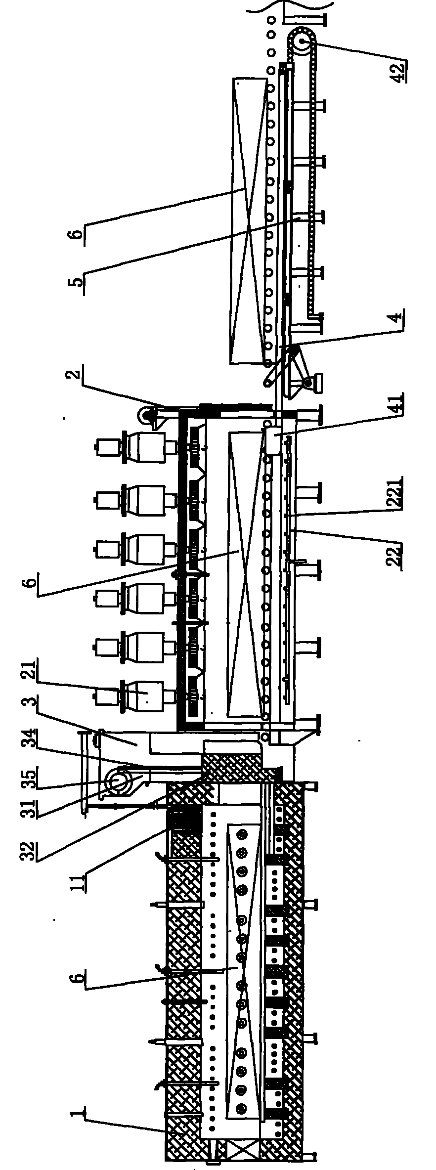
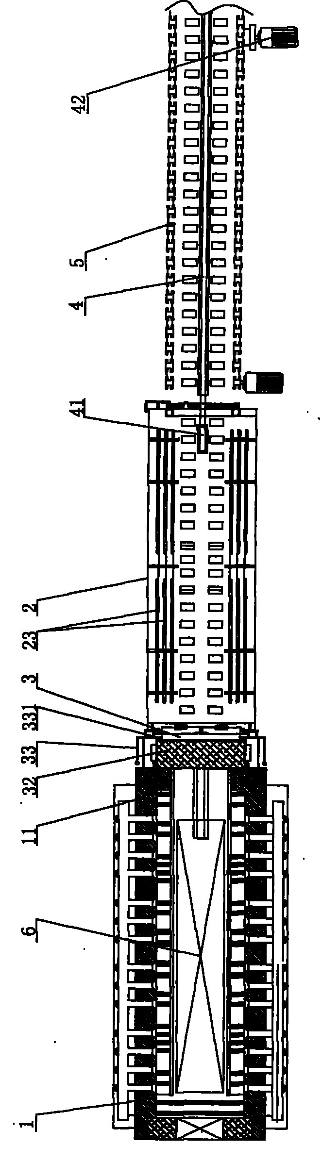
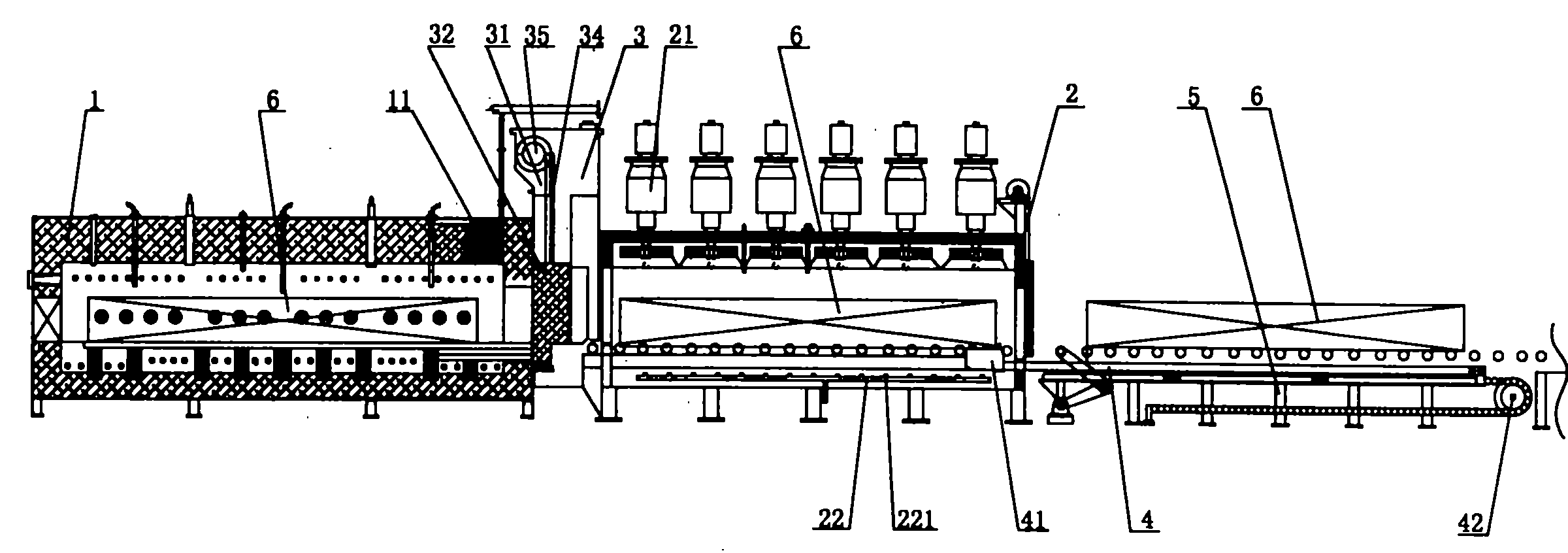
[0017] like figure 1 , figure 2 The shown structure schematic diagram of the present invention comprises a brazing furnace 1, a protective atmosphere system and a heating system are arranged in the brazing furnace 1, a quenching furnace 2 is provided at one end of the discharge port of the brazing furnace 1, and a quenching furnace 2 is arranged on the top of the quenching furnace 2 A circulating fan 21, a ventilation duct 22 is laid on the bottom of the quenching furnace 2, a nozzle 221 is arranged on the ventilation duct 22, and cooling water pipes 23 are arranged on both sides of the quenching furnace 2 to ensure a stable protective atmosphere in the entire quenching furnace and low temperature state, one end of the discharge port of the quenching furnace 2 is connected to the conveying platform 5, and the conveying platform 5 is provided with a push rod mechanism. Furnace 2 housing and connected push head 41.

[0018] A gate mechanism is provided between the feed port ...


PUM


Abstract

The invention discloses an integral device for a braze welding technique, which includes a braze welding furnace and a quenching furnace; the discharge opening of the braze welding furnace and the feed opening of the quenching furnace are connected by a seal connection part which is provided with a strobe mechanism. In the invention, based on the existing braze welding furnace, the quenching furnace is combined with the braze welding furnace, thus realizing that the whole technical processes of braze welding, quenching and cooling are carried out in an closed environment with protection atmosphere; the welding lines of workpieces are tight and uniform with a smooth surface, thus not only simplifying the production technique, saving the working time, improving the production efficiency, but also reducing the manual working intensity and saving a workshop space. The integral device has the advantages of novel structure, high automatization degree, simple operation and wide application range.

Description

technical field [0001] The invention relates to a brazing device for hard alloy, carbon steel and other materials, in particular to a brazing process integrated device. Background technique [0002] The welding method of wetting the base metal with liquid brazing material and filling the interface gap of the workpiece and making it diffuse with the base metal is called brazing. The method of heating and brazing the assembled workpiece in a brazing furnace is called furnace Brazing has the characteristics of overall heating, uniform heating, and small deformation of the workpiece. The heating device is a brazing furnace. [0003] At present, there are generally two types of brazing furnaces for brazing in domestic furnaces: one is a vacuum furnace, which uses the evaporation of metals and their oxides when heated in a vacuum to destroy the oxide film on the surface, so as to achieve the effect of removing the film, which can effectively Prevent the metal to be welded from be...

Claims


Application Information

Patent Timeline
Patent Type & Authority Patents(China)
IPC IPC(8): B23K3/00B23K3/08B23K1/008C21D1/62C22F1/00
Inventor 章体
Owner 浙江华虹电炉有限公司
Why Eureka
Try Eureka