Desk type accurate punching machine

A precision punching and desktop technology, applied in the field of mechanical processing equipment, can solve the problems of large contact area, increased friction coefficient, high machining accuracy requirements of ball joints, and increased energy consumption of brake belts, achieving good braking performance and compact structure. , the effect of reducing resistance

Inactive Publication Date: 2009-02-11
宁波米斯克精密机械工程技术有限公司
View PDF1 Cites 10 Cited by
  • Summary
  • Abstract
  • Description
  • Claims
  • Application Information

AI Technical Summary

Problems solved by technology

[0002] At present, the commercially available desktop precision punching machines have brake parts and clutch parts that are split, and are installed on the front and rear ends of the frame respectively. The brake parts are brake bands, and both ends are fixed on the frame to form An annular ring, with the rotation of the crankshaft, is constantly in contact with the crankshaft part of the crankshaft, so no matter whether the flywheel controlled by the clutch is driven or separated from the crankshaft, the brake belt is always in working condition, which increases the wear of the brake belt and increases the energy. Consumption, after a long time, the braking effect will be inaccurate, so there are still hidden dangers of safety, and at the same time, the working efficiency is not ideal and the operating cost is increased
In addition, the sliding friction copper structure is adopted between the frame and the crankshaft parts, so the contact area is large, the friction coefficient increases, the lubrication is insufficient, and it is easy to generate heat, lock, and severe wear.
[0003] In addition, because of the connecting rod and slider, the ball joint structure is used to adjust the height of the desktop precision punching machine mold, but the ball joint rod requires high machining accuracy, is difficult to process, and the bottom dead center is unstable, so there is low stamping accuracy. , mold height adjustment is inconvenient and many other disadvantages

Method used


Image

  • Desk type accurate punching machine
  • Desk type accurate punching machine
  • Desk type accurate punching machine

Examples


Embodiment Construction

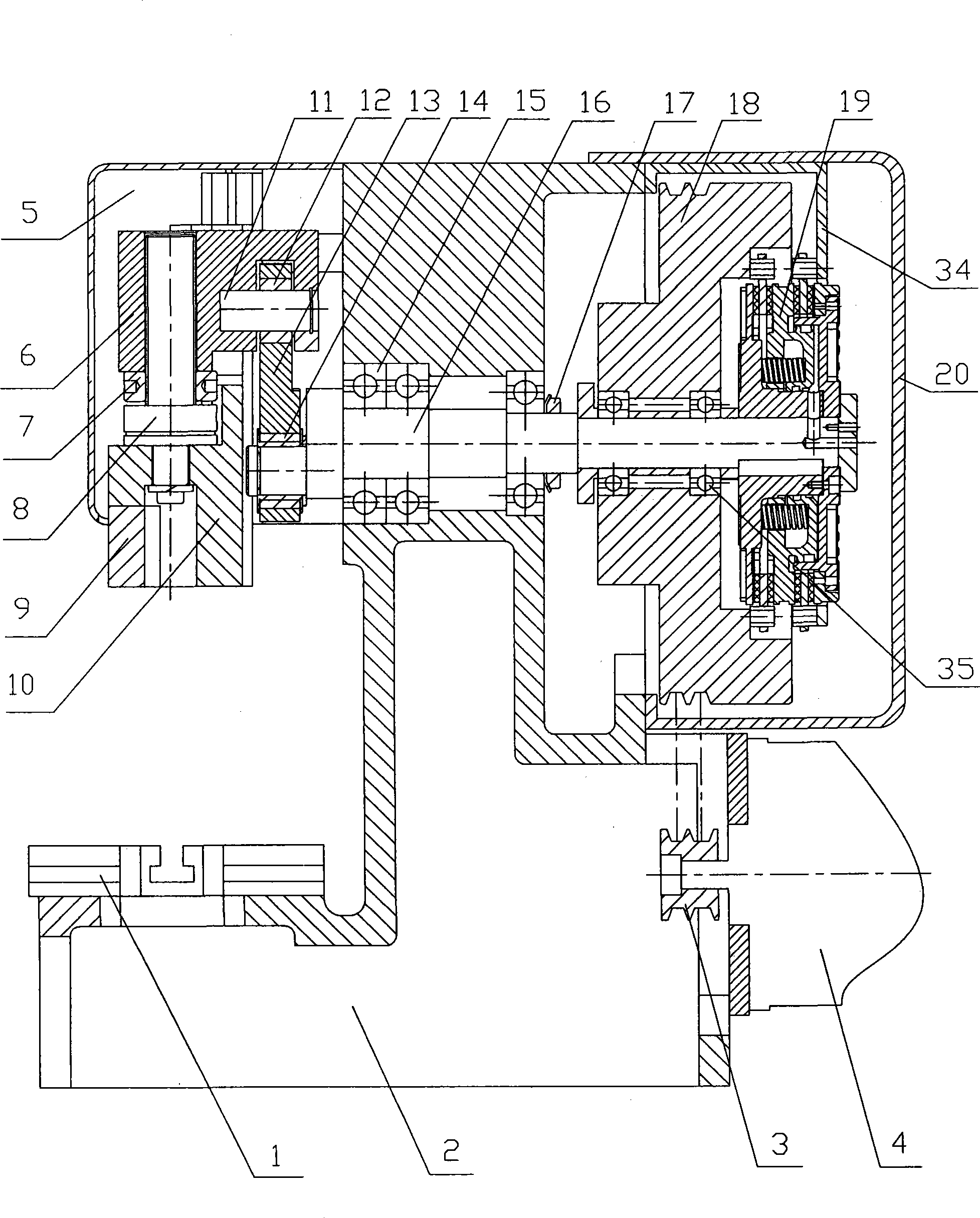
[0012] Embodiments of the present invention will be further described below in conjunction with the accompanying drawings.

[0013] Workbench 1 and motor 4 are fixedly installed on the surface and side wall of table body 2 respectively, crankshaft 16 is installed on table body 2 through bearing 15, flywheel 18 is installed on crankshaft 16 through flywheel bearing 35, in order to prevent axial movement Also be connected with stop nut 17 on the crankshaft of stage body place, motor 4 drives flywheel 18 by belt pulley 3, belt and rotates.

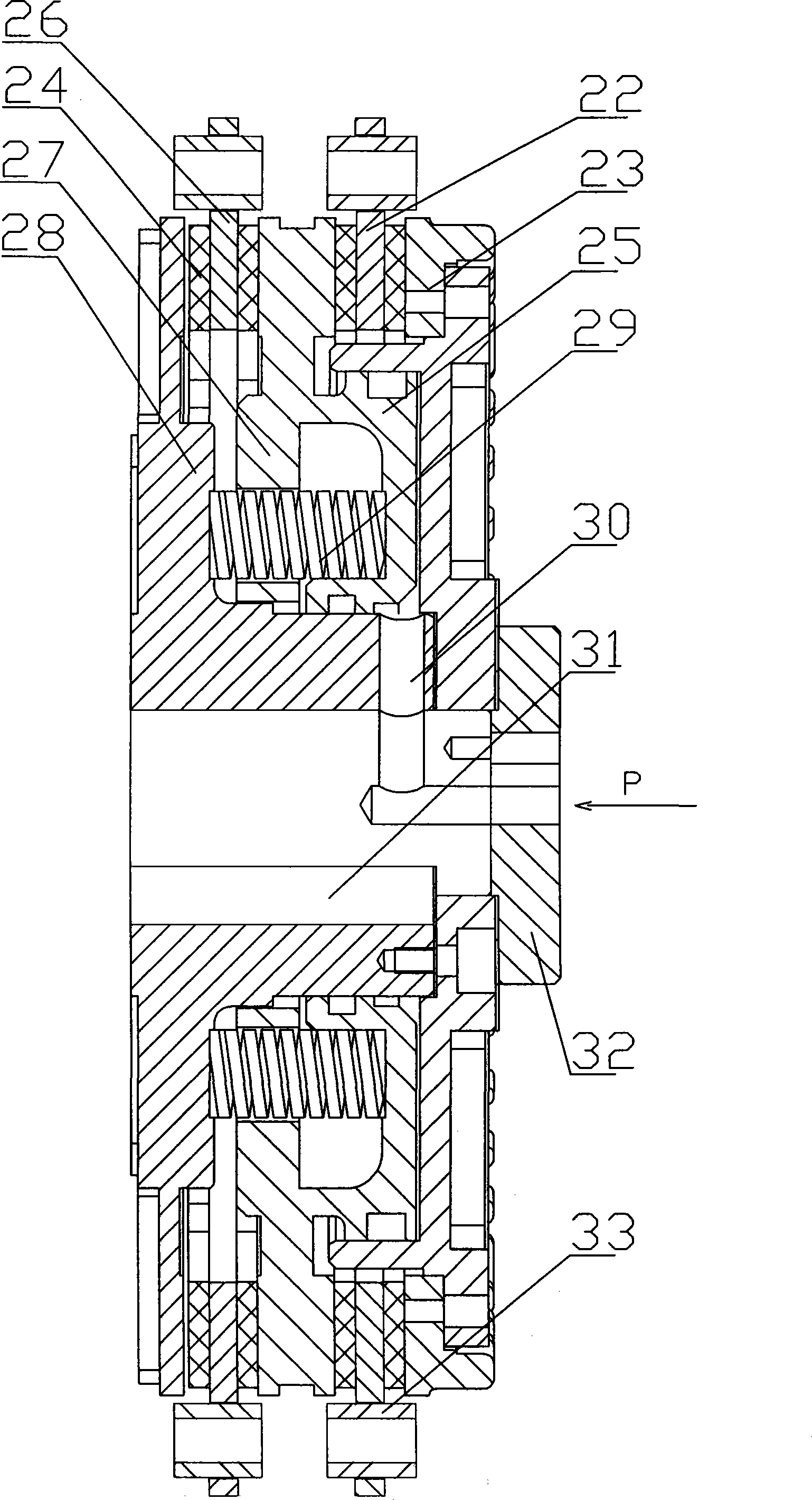
[0014] In the middle of the crankshaft 16 rear end, there is a vertically and horizontally connected blind hole for the air inlet P to be connected with the gas source.

[0015] There is an air inlet 30 on the surface of one side of the body 28 to communicate with the air inlet P, and the body is slippery matched with the piston 27 with a uniformly distributed spring 29. The blind holes on the body and the piston cooperate, the two side wall...


PUM


Abstract

The invention provides a table type precise punching machine which comprises a working table, a table body and a motor, wherein, clutch brake components are formed by the matching of a brake clutch pressure plate with brake blocks and a piston which is arranged in a cylinder of a body and provided with a spring; the brake clutch pressure plate is fixed on a fly wheel and the table body; a crank shaft and the body which is connected on the crank shaft are provided with an air inlet and an air inlet hole which are connected with a gas source; a connecting rod slide block device is formed by the following steps: the upper end of the connecting rod with a joint bearing is connected with an adjustment slide block by a pin, the lower end of the connecting rod with the bearing is connected with the crank shaft, and the slide block and the adjustment slide block are connected into a whole by a saw tooth with a nut and a screw rod, and the slide block and a guide rail are matched. The clutch and the brake which are originally installed in a dispersion way are integrated to be centrally installed and are compact in structure, small in volume, good in braking performance and safe and flexible in use; the lubrication of each rotational position is ensured by a rolling bear, thus sufficiently reducing the resistance and improving the working efficiency; the connecting rod slide block device greatly reduces the volume of the whole machine and is easy to be processed and installed, thus improving the installation precision and causing a die to be simple and convenient in adjustment and operation.

Description

technical field [0001] The invention relates to a mechanical processing equipment, in particular to a desktop precision punching machine with small volume, convenient use, safety and high punching precision. Background technique [0002] At present, the commercially available desktop precision punching machines have brake parts and clutch parts that are split, and are installed on the front and rear ends of the frame respectively. The brake parts are brake bands, and both ends are fixed on the frame to form An annular ring, with the rotation of the crankshaft, is constantly in contact with the crankshaft part of the crankshaft, so no matter whether the flywheel controlled by the clutch is driven or separated from the crankshaft, the brake belt is always in working condition, which increases the wear of the brake belt and increases the energy. Consumption, after a long time, the braking effect is not accurate, so there is also a potential safety hazard, and the unsatisfactory...

Claims


Application Information

Patent Timeline
Patent Type & Authority Applications(China)
IPC IPC(8): B21D22/02
Inventor 王赛珍
Owner 宁波米斯克精密机械工程技术有限公司
Why Eureka
Try Eureka