
Pneumatic electrothermal stewing implement

A technology for cooking utensils and electric heaters, which is applied to cooking utensils, household utensils, kitchen utensils, etc., can solve the problems of high cost, single function and high energy consumption, and achieve the effects of saving energy, improving stability and reducing heat of vaporization

Active Publication Date: 2013-09-04
王永光
View PDF0 Cites 0 Cited by
  • Summary
  • Abstract
  • Description
  • Claims
  • Application Information

AI Technical Summary

Problems solved by technology

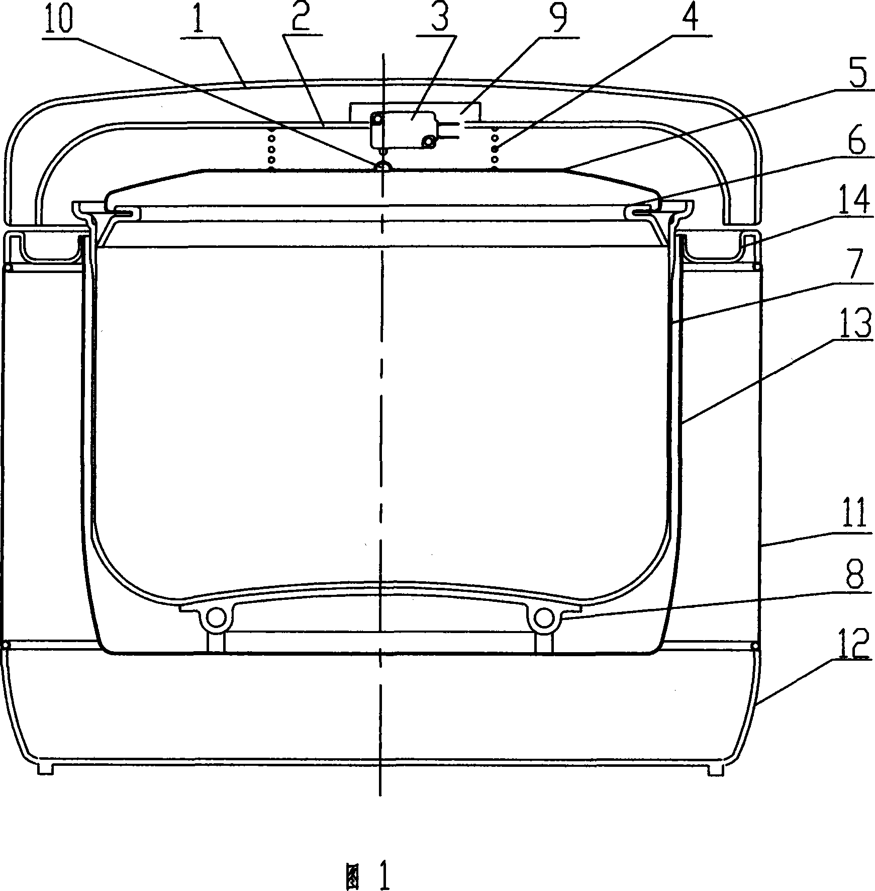
[0003] In order to solve the existing problems of single function, high energy consumption, complex structure, high cost, poor cooking effect and overflow of porridge and soup when boiling in saturation, according to the relevant national standards, the electric rice cooker should be operated at an atmospheric pressure of 86kPa ~ 106kPa environmental work requirements, the present invention utilizes the thermophysical characteristics of water boiling, combined with steam power control technology, proposes a steam-driven electric heating cooking appliance working under normal pressure, which includes: pot cover, plastic cover lining , inner pot, electric heater; the inner pot is set on the electric heater

Method used


Image

  • Pneumatic electrothermal stewing implement
  • Pneumatic electrothermal stewing implement
  • Pneumatic electrothermal stewing implement

Examples


Embodiment 1

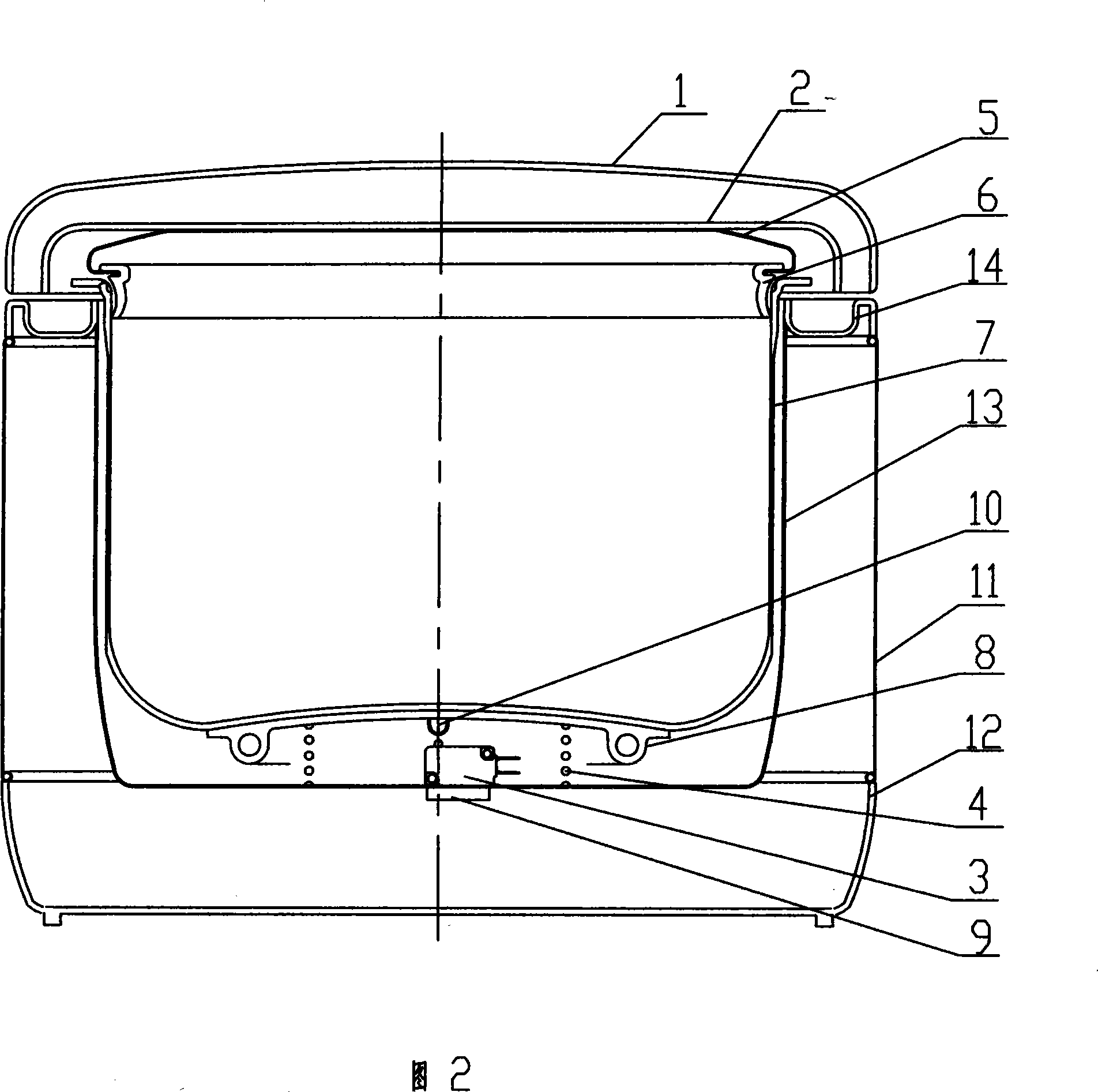
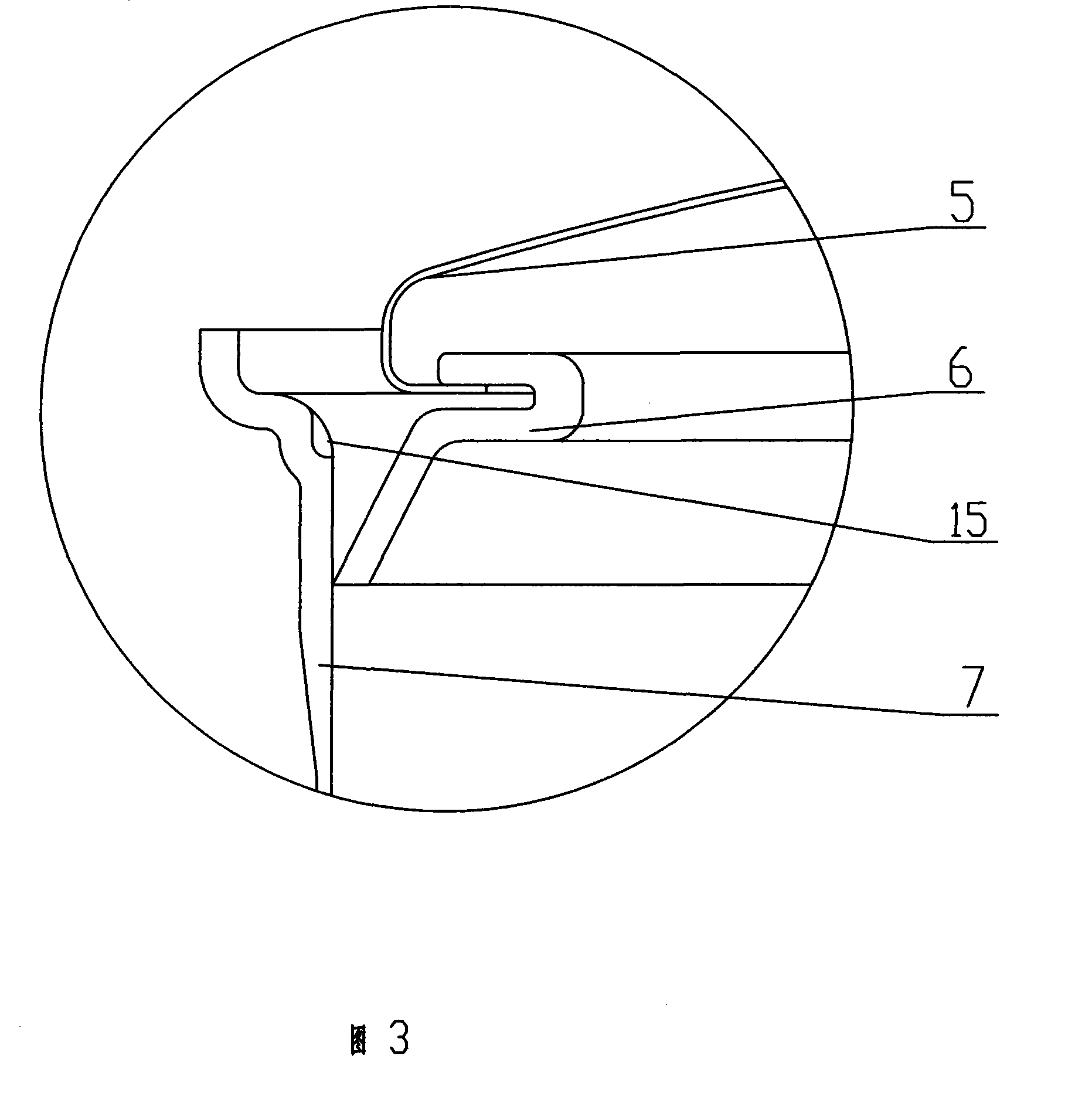
[0018] Embodiment 1: the overall structural design of product of the present invention, except implementing relevant technical parts with this technical scheme, other parts are as plastic cover 1, plastic cover liner 2, outer pot 13, shell 11, base 12 and pot cover parts and The connection structure of the inner pot parts, etc., can be designed with reference to the relevant parts of the existing conjoined electric rice cooker product. In practice, the pot lid 5 can be made of a high-quality stainless steel plate or high-quality alloy aluminum plate with a thickness of about 0.3 mm, and its outer edge size and shape should cooperate with the sealing ring 6 to meet the requirements of dynamic sealing connection. Switch 3 can select the monostable type microswitch that adopts on the existing electric cooker for use, and its feature is to change heating state with the change of driving force, it is fixedly arranged on the plastic cover lining 2 and notices waterproof. At the posi...

Embodiment 2

[0021] Embodiment 2: The difference between Embodiment 2 and Embodiment 1 is that the steam power control device is arranged below the electric heater 8 . Since the bottom of the inner pot 7 is in contact with the upper surface of the electric heater 8, the steam power in the pot can be transmitted to the electric heater 8 through the bottom of the inner pot, so that it moves downwards with the inner pot 7, thereby realizing the present invention technical solutions. When implementing the scheme of placing the steam power control device below, in order to offset the sum of the gravity of the inner pot 7 (gravity about 500g·f), food (gravity up to 4kg·f), electric heater 8 (gravity about 250g·f), etc., it is necessary to set The elastic element 4 (whose elastic force should be about 5kg·f) realizes the force balance requirement, so as to obtain the required starting control sensitivity. Such as figure 2 As shown, one end of the elastic element 4 is arranged below the electri...

Embodiment 3

[0022] Embodiment 3: The electric heater 8 in the present invention can be an electromagnetic electric heater or a radiation electric heater. The inner pot 7 is not in contact with the electric heater 8 for heat transfer. When adopting this technical solution, the following options can be selected: one is that the steam power control device is placed on the top, and the setting method and position can refer to embodiment 1. The pot edge of inner pot 7 is supported on the pot edge of outer pot 13 (or the corresponding position of outer pot cover 14), and in work, inner pot 7 is in relatively static state. The electric heater 8 is fixedly arranged between the bottom of the inner pot 7 and the bottom of the outer pot 13 . The 2nd, steam power control device is put down, and pot cover 5 is in static state. Elastic element 4 is arranged at the bottom of outer pot 13, and inner pot 7 is mounted on elastic element 4. In practice, the diameter-reducing part of inner pot 7 bottom can ...


PUM


Abstract

The invention provides a turbine driven electrothermal cooking apparatus; the invention belongs to the turbine driven electrothermal cooking apparatuses used in kitchen, which utilizes the product technology that temperature is controlled by steam power to facilitate the work of an electric cooker under normal atmospheric pressure. The invention comprises a cooker cover, an internal pot and an electric heater, wherein the internal pot is arranged on the electric cooker; the invention also comprises a dynamic control device comprising a fixed structure part, a switch, a dynamic transmitting part, wherein, the switch is in series connection with the electric heater and then connected with a power supply. The invention solves the problems of complicated structure, high cost, bad effect of cooking, high energy consumption, overflowing of gruel and soup, etc.Compared with the prior art, the invention is not only simple in structure and low in cost, but also has the advantages of energy conservation, multifunction, reliability, etc., and the invention can also be designed integrating with the present electric cooker structure. Therefore, the invention has wide development prospect in the application of the electric cooking apparatuses.

Description

Technical field: [0001] The invention belongs to electric heating cooking utensils for kitchens, and is an electric rice cooker product technology which utilizes steam power to control cooking temperature and works under normal pressure. Background technique: [0002] The existing magnetic steel Curie-type temperature-controlled rice cooker has been available for more than 40 years. Although it is an excellent product for cooking rice, based on the working principle of the magnetic steel temperature limiter, the water in the pot needs to be boiled dry, and the temperature at the bottom of the pot exceeds After 100℃, the power can be cut off. During this process, the saturated boiling of water will take away a large amount of heat of vaporization, resulting in a great loss of energy. Since the rice will be stewed by the residual heat of the electric heating plate after the power failure, the electric heating plate must be made large enough to store the energy that can stew t...

Claims


Application Information

Patent Timeline
Patent Type & Authority Patents(China)
IPC IPC(8): A47J27/00A47J36/32
Inventor 王永光
Owner 王永光
Learn More