
Method for producing biomass carbonization carbon and biomass gas, and rapid thermal decomposition coke oven

A biomass gas and biomass technology, which is applied in the fields of biofuels, special forms of dry distillation, combined combustion mitigation, etc., can solve the problems of uneven distribution of high-temperature gas, high price, and large unsafe factors, and achieves loose and porous carbon. Good surface properties, high carbon content effect

Inactive Publication Date: 2008-06-11
韩璋鑫
View PDF0 Cites 29 Cited by
  • Summary
  • Abstract
  • Description
  • Claims
  • Application Information

AI Technical Summary

Problems solved by technology

[0002] In the production method of the double-cavity carbonization furnace in the prior art, an independent gasification furnace chamber and a carbonization furnace chamber are arranged side by side in the furnace, and agricultural waste such as biomass straw is processed, chopped and dried during operation. Adding separate gasification furnace cavity and carbonization furnace cavity respectively, sucking the high-temperature gas generated in the gasification furnace cavity into the carbonization furnace cavity next to it, carbonizing the material into biomass charcoal and biomass gas , the composition of biochar produced by this method is basically the same as that of wood charcoal. However, there are still some defects in the industrial operation as follows: since the gasification furnace chamber and the carbonization furnace chamber in the furnace are set separately and side by side, they will be separated from each other during operation. When the high-temperature gas generated in the gasification furnace cavity enters the adjacent carbonization furnace cavity to dry-distill carbonized materials, the high-temperature gas drawn into the carbonization furnace cavity is unevenly distributed due to the long distance between the two furnace chambers. The carbonization effect on the side where the two chambers are close is ideal, but on the other side where the two chambers are far away, the carbonization effect is not ideal due to insufficient diffusion of high-temperature gas, and the phenomenon of half-generated charcoal occurs, so the quality of the carbonized product is unstable.
[0003] Due to the large volume of the gasification furnace chamber and the carbonization furnace chamber that are arranged side by side in the furnace, the amount of steel consumed is large, and the cost of the furnace body is high. Strictly require the performance of sealed operation to be poor, resulting in greater unsafe factors
[0004] In the prior art, there are also methods for producing biomass carbonization gas and a backfire biomass carbonization gas generator. After molding, they are respectively added to the upper gasification chamber and the lower carbonization chamber set in the furnace. During operation, the high-temperature gas generated in the upper gasification chamber in the furnace is directly sucked into the lower carbonization chamber of the furnace to dry-distill the carbonized materials. Carbonization produces biochar, and at the same time releases methane CH in volatile components 4 , hydrogen H 2 , Hydrocarbon C h Hmm and other high-calorific hydrocarbons are mixed with the gas entering the gasification chamber on the upper layer of the furnace, and the calorific value in the gas is as high as 5000-6000kJ / m 3 , the biomass charcoal and biomass gas produced by this method are ideal, but there are still some difficulties and defects in the manufacturing process of the furnace, because the furnace is equipped with an upper gasification chamber and a lower carbonization chamber. The rows are all operating at high temperature, and the quality requirements for the high-temperature resistant stainless steel materials used are high, the price is expensive, and the manufacturing process of the furnace body is complicated.

Method used


Image

  • Method for producing biomass carbonization carbon and biomass gas, and rapid thermal decomposition coke oven

Examples


Embodiment 1

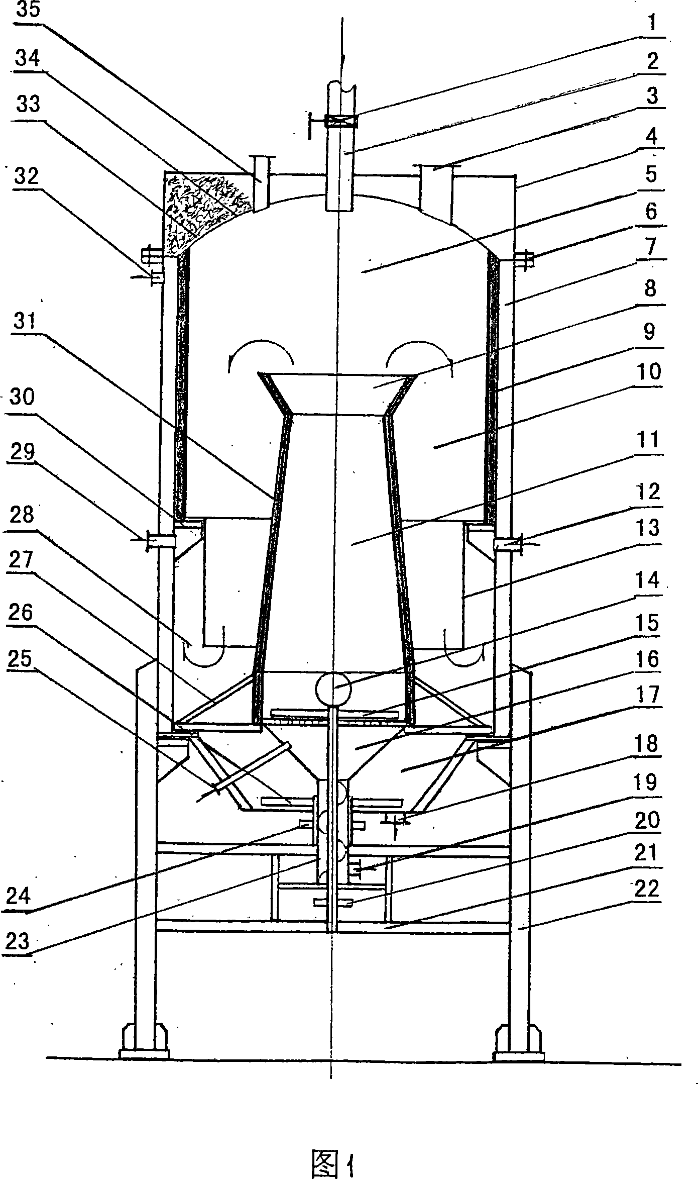
[0015]Materials such as rice husks and fruit husks (moisture content is controlled at about 10%) are fed into the upper part of the furnace (Φ1.6 meters in diameter and 5.3 meters in height) through the feeding nozzle 2 in the middle of the upper part of the upper furnace roof 4. The collection chamber 5 is distributed into the dry distillation carbonization chamber 10 and the gasification reaction chamber 11. After the materials are filled, the feeding sealing valve 1 is closed, the air inlet nozzle arranged at the bottom of the gasification reaction chamber is opened, and the gasification chamber arranged outside the furnace is activated. Negative-pressure Roots blower, then open the furnace door 14 arranged at the bottom of the gasification reaction chamber; ignite the gasified material in the gasification reaction chamber, and close the furnace door 14; under the action of the negative-pressure Roots blower outside the furnace, suction The 500-700C high-temperature oxygen-d...

Embodiment 2

[0018] Cotton stalks, corn stalks, soybean stalks, and sorghum stalks are used as the main materials. After processing and cutting, the length is controlled at 30-50 mm, and the water content is controlled at about 10%. 2 Feed into the furnace (Φ diameter 2.4 meters, furnace body height 5.6 meters) in the upper collection chamber 5 in the furnace and distribute into the retort carbonization chamber 10 and gasification reaction chamber 11. After the materials are filled, close the feeding sealing valve 1 and open The air inlet nozzle arranged at the bottom of the gasification reaction chamber starts the negative pressure Roots blower arranged outside the furnace, and then opens the furnace door 14 arranged at the lower part of the gasification reaction chamber; ignites the gasified materials in the gasification reaction chamber, and closes Furnace door 14; under the action of the negative pressure Roots blower outside the furnace, the 500-700C ° high-temperature oxygen-deficient...

Embodiment 3

[0021] The main materials are rice straw, thatch, wheat straw, rapeseed stalk, and bagasse. After they are chopped or crushed, dried, they are mechanically extruded into block or rod-shaped materials. The water content is controlled at about 10%. The upper middle charging nozzle 2 arranged on the upper furnace roof 4 is fed into the furnace (3.3 meters in diameter, 5.8 meters in height of the furnace body) and the upper collection chamber 5 in the furnace is distributed into the dry distillation carbonization chamber 10 and the gasification reaction chamber 11. After the material is filled up, close the feeding sealing valve 1, open the air inlet nozzle arranged at the bottom of the gasification reaction chamber, start the negative pressure Roots blower arranged outside the furnace, and then open the furnace door 14 arranged at the lower part of the gasification reaction chamber ignite the gasified material in the lower part of the gasification reaction chamber, and close the f...


PUM


Abstract

The invention relates to a method for producing biomass dry distillation carbon and biomass fuel gas and a rapid pyrolysis carbonized oven, materials of biomass straw, and tree branches, etc. are utilized to be added into the oven through a material filling pipe mouth, after the over is filled with the materials, an air inlet pipe mouth arranged at the bottom part of a gasification reaction chamber in the oven is opened, a negative pressure Roots blower fan arranged outside the oven is started, a oven door arranged at the lower part of the gasification reaction chamber is opened, the oven door is closed after gasification materials filled at the lower part of the gasification reaction chamber are ignited, generated combustible gas in the gasification reaction chamber is sucked to be diffused in a dry distillation carbonized chamber arranged on the periphery of the gasification reaction chamber through a fuel gas diffusing opening arranged at the upper part of a gasification chamber, thus carbonized materials are retorted into biomass carbon, simultaneously after methane, carbon monoxide, hydrogen, and hydrocarbon ChHmm in volatile component are released to be mixed with the flue gas generated in the gasification reaction chamber, the heat value of the flue gas is as high as about 6000 kJ / m3, after the purification and the treatment, the flue gas is the clean, inexpensive, and good quality biomass flue gas used for a flue gas electric generator group to generate power or provided for the burning of town dweller.

Description

technical field [0001] The invention relates to a method of setting a dry distillation carbonization chamber in a furnace for agricultural and forestry waste such as biomass straws, branches, fruit shells, and rice husks, and setting a gasification reaction chamber in the middle of the dry distillation carbonization chamber to produce biomass dry distillation charcoal and Biomass gas method and fast pyrolysis carbonization furnace. Background technique: [0002] In the production method of the double-cavity carbonization furnace in the prior art, an independent gasification furnace chamber and a carbonization furnace chamber are arranged side by side in the furnace, and agricultural waste such as biomass straw is processed, chopped and dried during operation. Adding separate gasification furnace cavity and carbonization furnace cavity respectively, sucking the high-temperature gas generated in the gasification furnace cavity into the carbonization furnace cavity next to it, ...

Claims


Application Information

Patent Timeline
IPC IPC(8): C10B53/02
CPCY02E20/18Y02E50/14Y02E50/10
Inventor 韩璋鑫
Owner 韩璋鑫
Learn More