
Bridge initiative bump-elimination structure

An active bridge technology, applied to roads, road safety devices, roads, etc., can solve the problems of high cost of bridges, and achieve the effect of improving anti-collision ability, high safety, and good emergency response

Inactive Publication Date: 2008-05-14
赵颖寅
View PDF1 Cites 4 Cited by
  • Summary
  • Abstract
  • Description
  • Claims
  • Application Information

AI Technical Summary

Problems solved by technology

[0004] Another example is the patent No. ZL2006155224.5 of the Chinese invention application patent "Bridge Anti-Collision Cushion Pile". This technology protects the pier from damage at the expense of the fender pile. When the collision force is huge, the fender pile cannot withstand it and is hit. In this case, the bridge pier only bears less than half of the impact force, and the rest is eliminated by the damping of the mud layer, and it meets the specification that the bridge pier can ignore the impact of the ship when there is an anti-collision protective structure separate from the pier abutment; but For the ship involved in the accident, there is no such thing as unlucky. In addition to eliminating a part of the impact force due to the rotation of the fender, it must bear all the force generated by the collision. Not as strong as an egg shell, and if the ship involved sinks or leaks, the environmental consequences are huge, possibly more costly and irreparable than damaged bridges

Method used


Image

  • Bridge initiative bump-elimination structure
  • Bridge initiative bump-elimination structure
  • Bridge initiative bump-elimination structure

Examples


Embodiment Construction

[0024] The present invention will be further described in detail below in conjunction with the accompanying drawings and embodiments.

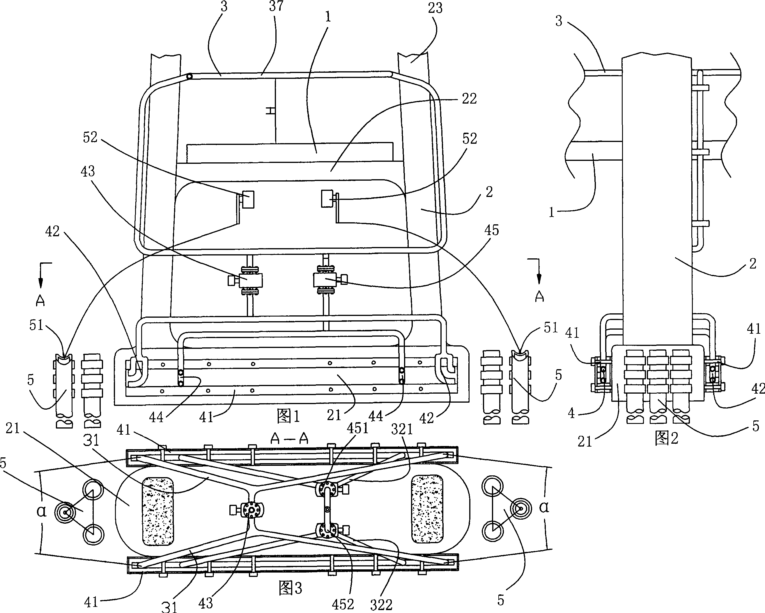
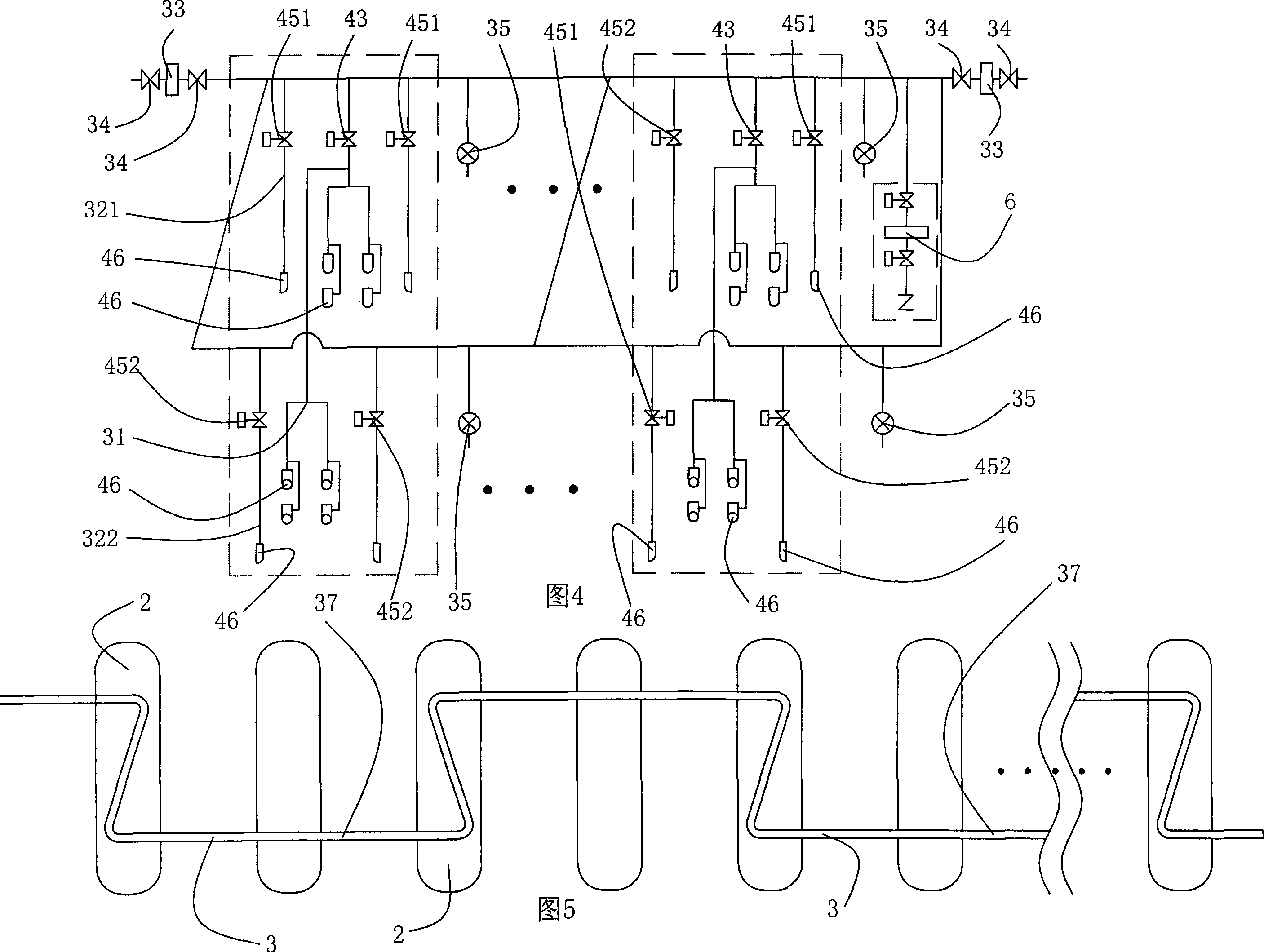
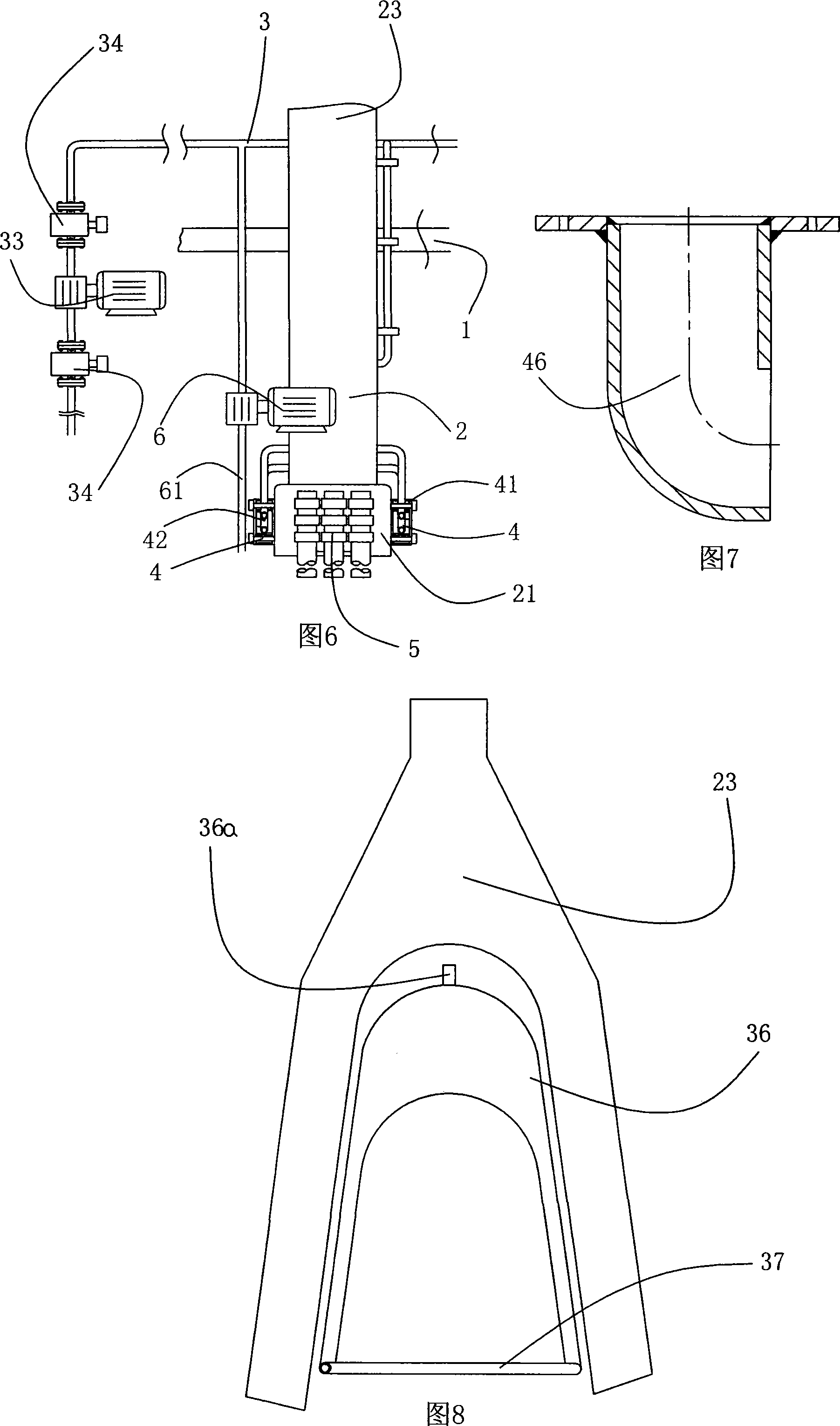
[0025] The embodiment shown in Fig. 1 to Fig. 8, reference number explanation: bridge deck body 1, pier 2, cap 21, pier frame 22, bridge tower 23, water supply pipe system 3, longitudinal water supply pipe 31, left horizontal water supply pipe 321, right horizontal water supply pipe 322, shore water pump 33, gate valve 34, water flow connection outlet 35, return pipe 36, air vent 36a, water storage pipe 37, injection mechanism 4, mounting frame 41, longitudinal injection pipe 42, longitudinal machine-controlled valve 43 , horizontal injection pipe 44, horizontal mechanical control valve 45, left horizontal mechanical control valve 451, right horizontal mechanical control valve 452, water nozzle 46, protection pile group 5, weight 51, water flow sensor 52, emergency water pump mechanism 6, water absorption Tube 61.

[0026] In the embodiment o...


PUM


Abstract

The invention discloses an initiative collision-eliminating structure of a bridge, which comprises a water supply pipe system for water storing laid on at least a pier. The upper part of the water supply pipe system is positioned above open traffic height of a bridge deck body; besides, the water supply pipe system extends downwards and is laid at two sides of the pier as well as communicated with a longitudinal control valve and a horizontal control valve. The longitudinal control valve is communicated with a longitudinal water supply pipe, and the horizontal control valve comprises a left horizontal control valve and a right horizontal control valve which control and are communicated with a left horizontal water supply pipe and a right horizontal water supply pipe. The longitudinal water supply pipe, the left horizontal water supply pipe and the right horizontal water supply pipe positioned at the side wall of the pier under the water are respectively communicated with at least an injection mechanism which can eject water flow with pressure, which can effectively protect the surrounding of the pier. An opposite acting force offset ejection method is adopted, which further improves anti-collision capacity of the pier; water medium stored in all weather has good emergency. An ashore water supply pump and an emergency water pump under the bridge are arranged, which can guarantee sufficient injection water.

Description

technical field [0001] The invention relates to the technical field of ship collision bridge protection, in particular to an active collision elimination structure of a bridge, which prevents or delays the collision between ships and bridges by spraying a large amount of pressurized water flow, thereby reducing or preventing damage to ships and bridges. Background technique [0002] With the rapid development of the economy and the continuous growth of water transportation, as well as the increase of bridges connecting roads on land, and the emergence of some super-large cross-sea and island-connecting bridges, the original large waterway has become narrow and large ships pass It seems more difficult when the ship is out of control due to technical failure or improper operation and other reasons, such accidents are reported in the media from time to time. [0003] At present, in the technology of preventing bridge collisions, strengthening the firmness of bridge piers is oft...

Claims


Application Information

Patent Timeline
Patent Type & Authority Applications(China)
IPC IPC(8): E01F15/14
Inventor 赵颖寅赵志平
Owner 赵颖寅
Learn More