
Steel blank heating device

A heating device and billet technology, which is used in the maintenance of heating chambers, lighting and heating equipment, furnace components, etc., can solve the problems of less flow heat and cannot be heated, and achieve the effect of good durability

Inactive Publication Date: 2008-04-02
CHUGAI RO CO LTD
View PDF2 Cites 9 Cited by
  • Summary
  • Abstract
  • Description
  • Claims
  • Application Information

AI Technical Summary

Problems solved by technology

However, the flame from the burner is a combustion method using air, so there is little convective heat, and it cannot be heated in a short time like the electromagnetic induction heating method

Method used


Image

  • Steel blank heating device
  • Steel blank heating device
  • Steel blank heating device

Examples


Embodiment Construction

[0025] Hereinafter, embodiments of the present invention will be described with reference to the drawings.

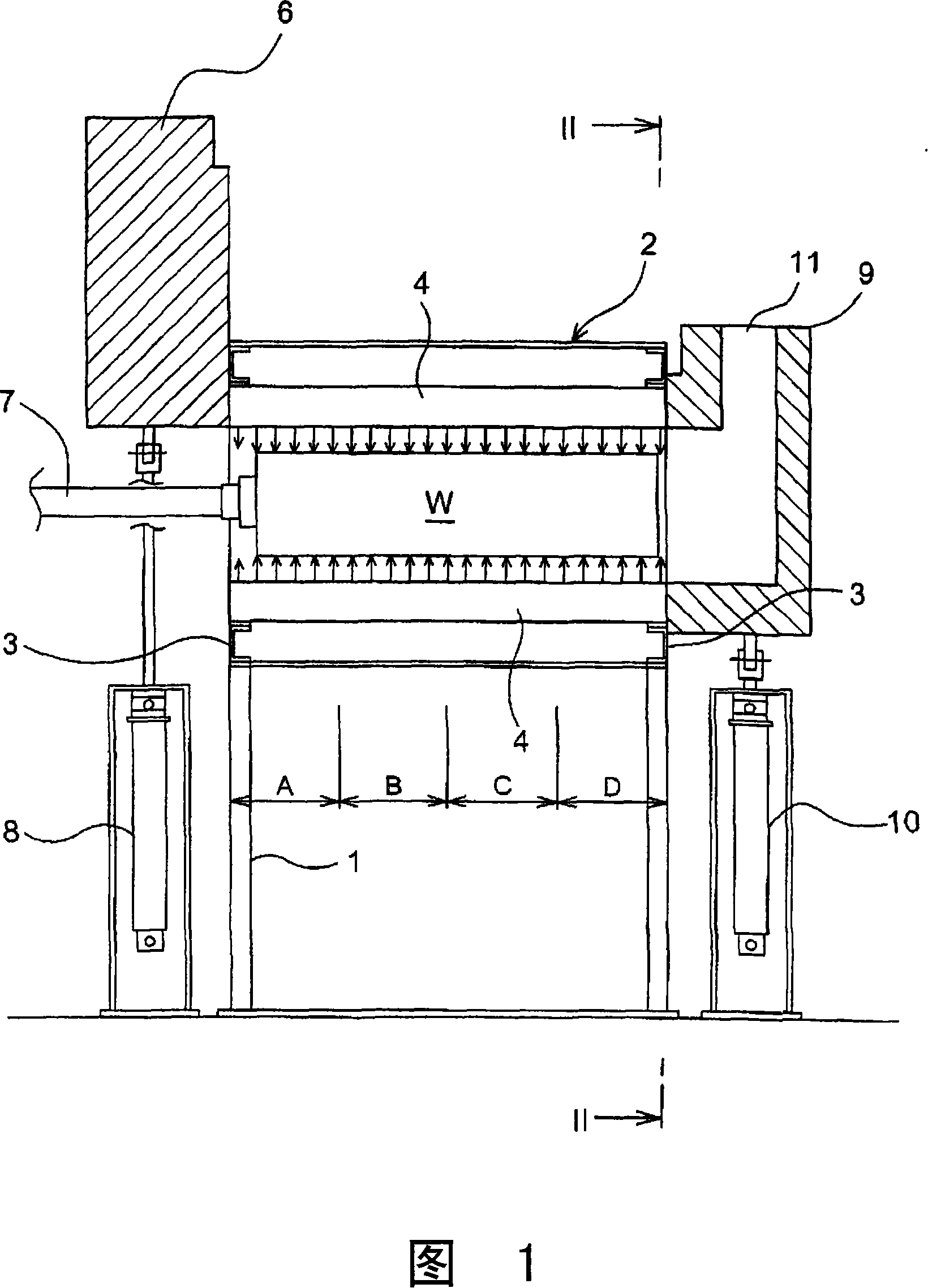
[0026] Fig. 1 and Fig. 2 show a heating apparatus for a slab W of the present invention.

[0027] The heating device has a body casing 2 provided on a stand 1 . The main body case 2 has an inverted U-shaped steel frame body 3 on the loading side and the pulling side of the billet W. Inside these frames 3, a plurality of (six in the embodiment) oxygen or oxygen-enriched burners 4 (hereinafter simply referred to as burner units) of a water-cooled structure supported at both ends are mounted. The burner units 4 are arranged at equal intervals in the circumferential direction, and extend in the longitudinal direction of the main body casing 2 , that is, from the insertion side to the extraction side. The main body casing 2 has no furnace wall, and is in a state in which the inside and the outside communicate with each other, and the burner unit 4 is installed in a state o...


PUM


Abstract

A billet heating mechanism comprises a body casing (2) composed of a frame (3) without furnace wall and with communicated inside and outside; a slide track (5) for supporting the billet (W) filled in the body casing (2) under the atmosphere condition; and a plurality of pure oxygen or oxygen boosting combustors (4) arranged on the body casing (2) for making the burning flame to strike the total length and full circumference of the billet (W) to heat the billet (W). The ratio of the diameter (D) of the nozzle (12) of the combustor (4) and the distance (L) between the outer surface of the billet (W) and the nozzle (12) is defined from 0.02 to 0.04, the interspace (P) between the nozzles 12 is 30 to 50 times of the diameter (D) of the nozzle. Adopting the invention, the heating ability and heat efficiency exceed the electromagnetic induction heating mode can be realized.

Description

technical field [0001] The present invention relates to a heating apparatus for a billet for extrusion molding of an aluminum alloy, a copper alloy, or the like. Background technique [0002] A billet for extrusion (hereinafter referred to as a billet) made of a round bar such as an aluminum alloy or copper alloy billet produced by continuous casting is heated by a billet heating device to the extrusion forming temperature as a whole. The step is formed into a predetermined shape by an extrusion molding machine. [0003] Conventionally, as a method for heating a slab, there are an electromagnetic induction heating method and a combustion heating method by a burner. The electromagnetic induction heating method has a large heating capacity, but has the disadvantage of high power consumption and high operating costs. Compared with the electromagnetic induction heating method, the combustion heating method by the burner has a low operating cost, but the heating capacity is sma...

Claims


Application Information

Patent Timeline
IPC IPC(8): B21C29/00B21J1/06C21D1/52F27B17/00F27D3/00F27D5/00
CPCB21J17/00F27D3/024F27D7/02F27D99/0033
Inventor 藤井邦夫谷山公勇友泽健一
Owner CHUGAI RO CO LTD
Learn More