
Method for on-line monitoring lens astigmatism

A kind of astigmatism and lens technology, applied in the field of lens astigmatism, can solve the problems of wasting production time and affecting the control accuracy of CD, so as to reduce the process cost, make up for the problems of low production capacity utilization and machine number differences, and improve the effect of real-time monitoring

Inactive Publication Date: 2008-01-23
SHANGHAI HUAHONG GRACE SEMICON MFG CORP
View PDF0 Cites 4 Cited by
  • Summary
  • Abstract
  • Description
  • Claims
  • Application Information

AI Technical Summary

Problems solved by technology

The astigmatism of the lens group will cause the pattern on the silicon wafer to have differences in the X and Y directions, thus affecting the control accuracy of the CD in the process
Traditional measurement of lens astigmatism (astigmatism) must be performed by exposing the silicon wafer on the imaging platform or recording by the photodetector on the platform, both of which require the lithography machine to stop production, wasting production time

Method used

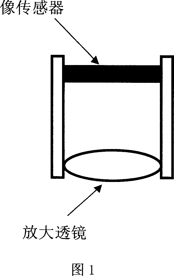
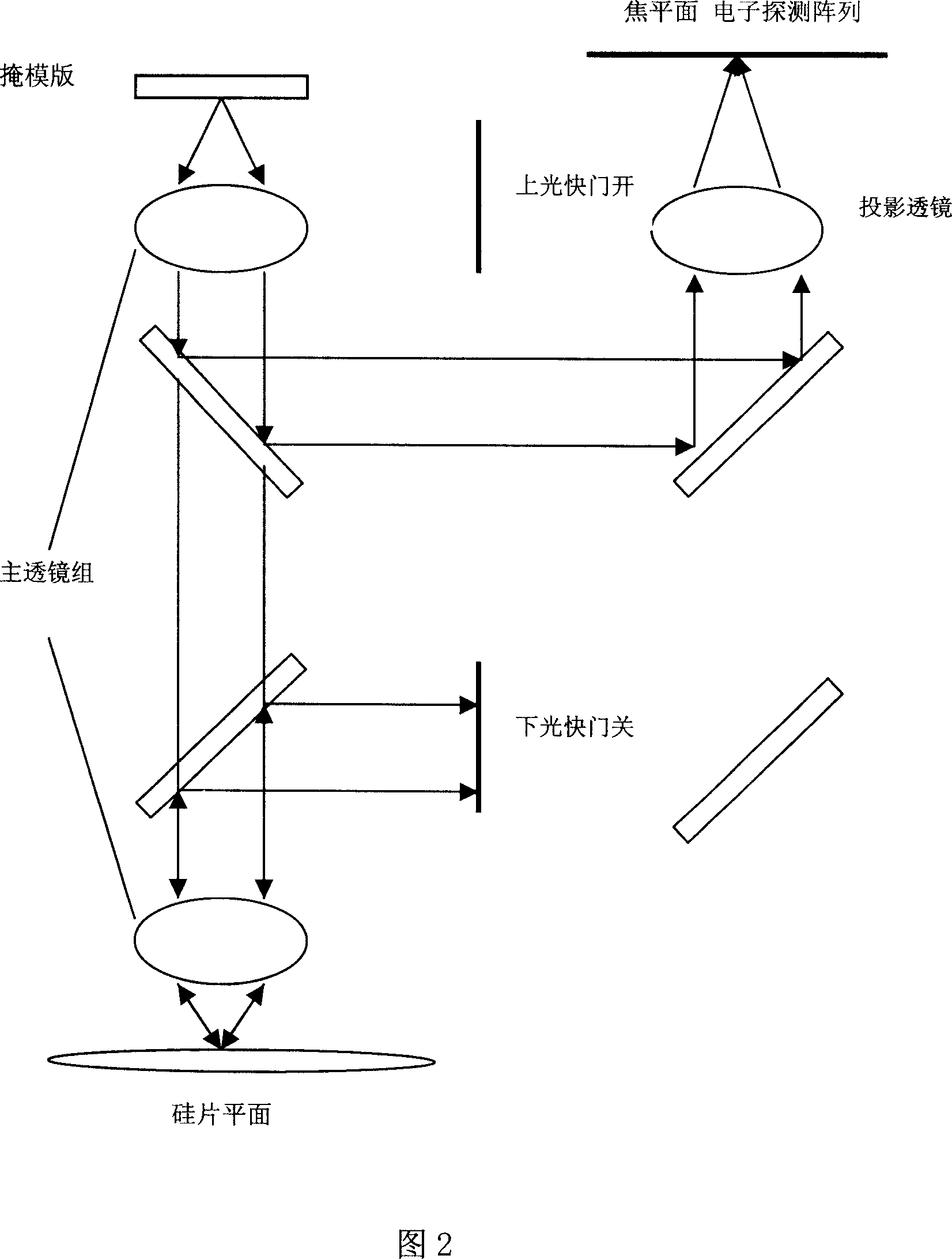
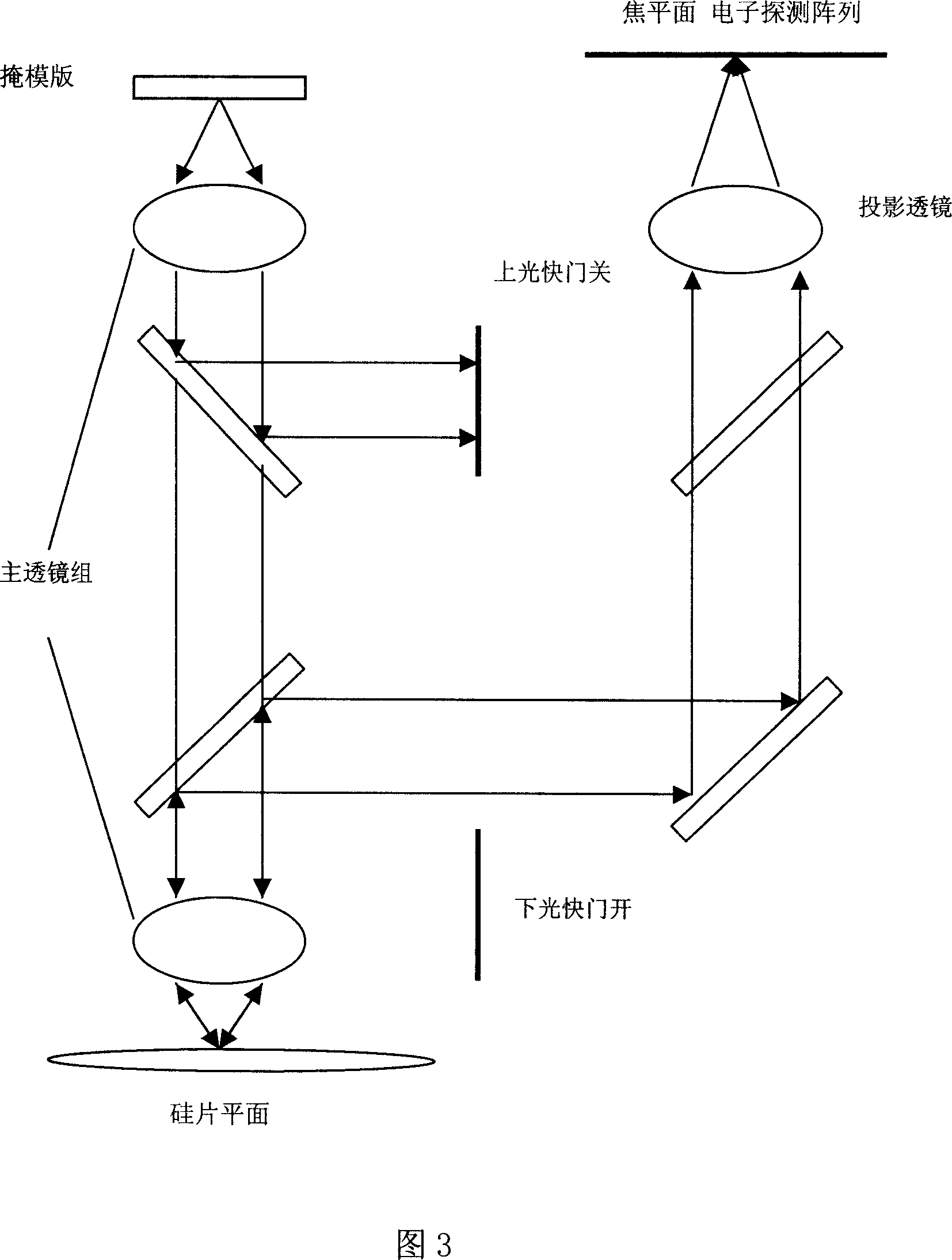

Image

  • Method for on-line monitoring lens astigmatism
  • Method for on-line monitoring lens astigmatism
  • Method for on-line monitoring lens astigmatism

Examples


Embodiment Construction

[0011] The implementation steps of the method of the present invention are:

[0012] First, use the lithography machine itself to expose light waves, and record the aerial images of the test structure on the mask plane and the test structure converging on the silicon wafer plane in a focal plane through a lens system while working. on the detector array. The wavelength of the exposure light wave can be the exposure wavelength of all photolithography equipment in the industry, such as g-line (436nm), i-line (365nm), KrF (248nm), ArF (193nm) or F2 (157nm). The lens system at least includes: a main lens group, a 45-degree angle beam splitter group near the Fourier plane, a 45-degree angle mirror group, a projection lens, a focal plane aerial image collection detector array, and an electronically controlled optical shutter group; wherein, The 45-degree angle beam-splitter plate group near the Fourier plane includes at least two upper and lower 45-degree angle beam-splitter plates...


PUM


Abstract

The utility model discloses an on-line monitoring method for monitoring the diffused light of the lens. The monitoring method thereof is listed as follows: the self-exposed light wave of the photo-etching machine can record the aerial images on the aerial image collecting & detecting array of a focal plane via a lens system. The aerial images are collected together on the mask plate surface and the silicon wafer plane, and then the comparison is made between the two groups of the aerial images which are recorded on the array of the electronic detector, so as to calculate out the object distance compensation of the lens along X-direction and Y-direction. As per the measuring result, a feedback system is used to adjust the environmental parameters of the lens assembly, so as to realize the compensation for the diffused light of the entire lens assembly. The lens system at least includes a main lens assembly, a 45o beam splitting plate series (close to the fourier plane), a 45o mirror assembly, a projection lens, a focal plane aerial image collecting & detecting array and a electronic controlled optical shutter series. This method solves the low utilization rate of productive capacity and the divergence of the machines arising from the traditional off-line measuring, so as to improve the reliability and the service efficiency of the photo-etching machine's accuracy control.

Description

technical field [0001] The invention relates to a method for on-line monitoring of lens astigmatism of a lens imaging system in a projection lithography machine. Background technique [0002] With the development of semiconductor technology and the progress of processing and manufacturing technology, the critical dimension (CD Critical Demotion) of semiconductor devices is getting smaller and smaller, and the difficulty of processing and manufacturing is also increasing. How to better and more precisely control the pattern on the silicon wafer is the key to improving the photolithography process. The astigmatism of the lens group will cause the pattern on the silicon wafer to have differences in the X and Y directions, thereby affecting the control accuracy of the CD in the process. Traditional measurement of lens astigmatism (astigmatism) must be performed by exposing the silicon wafer on the imaging platform or recording by the photodetector on the platform, both of which...

Claims


Application Information

Patent Timeline
Patent Type & Authority Applications(China)
IPC IPC(8): G03F7/20
Inventor 吴鹏伍强
Owner SHANGHAI HUAHONG GRACE SEMICON MFG CORP
Learn More