
Friction welding machine constant voltage variable hydraulic control system

A hydraulic control system, friction welding machine technology, applied in mechanical equipment, manufacturing tools, welding equipment, etc., can solve the problems of heat emission, oil temperature rise, large useless power, etc., to reduce power consumption, stabilize oil temperature, The effect of reducing power loss

Inactive Publication Date: 2009-12-23
NORTHWESTERN POLYTECHNICAL UNIV
View PDF6 Cites 0 Cited by
  • Summary
  • Abstract
  • Description
  • Claims
  • Application Information

AI Technical Summary

Problems solved by technology

As a result, the oil temperature rises too fast, the useless power is large, and the power utilization rate is very low
At the same time, the temperature of the hydraulic oil directly affects the viscosity of the hydraulic oil. The higher the temperature, the smaller the viscosity, the greater the change of the corresponding system leakage, and the greater the change of the flow resistance of the pipeline, which leads to changes in various parameters of the system and causes system failure. unstable, the control accuracy is correspondingly reduced
If a cooling system is used to control the oil temperature, electricity proportional to the heat production is required, and a large amount of heat is discharged into the atmosphere, which is not conducive to environmental protection

Method used


Image

  • Friction welding machine constant voltage variable hydraulic control system
  • Friction welding machine constant voltage variable hydraulic control system

Examples


Embodiment Construction

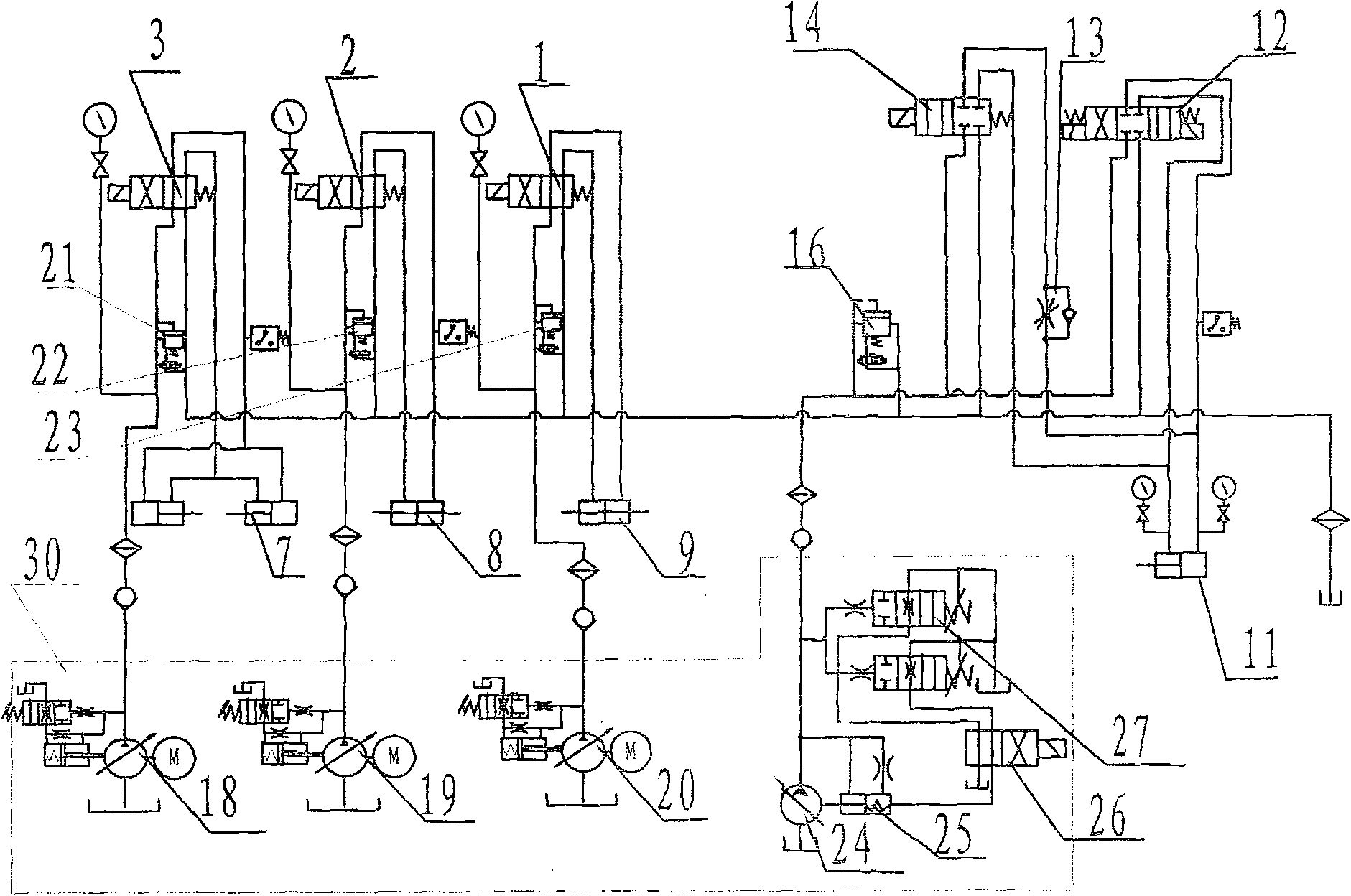
[0012] refer to figure 1 , the present invention includes a two-position four-way reversing valve, a pressure reducing valve, an oil cylinder, a three-position four-way reversing valve, a speed regulating valve, an electromagnetic overflow valve and a pump source device, and its pump source device 30 consists of a constant pressure variable pump A18 , constant pressure variable pump B19, constant pressure variable pump C20, and two-stage constant pressure variable pump 24 serve as pressure reducing valves D15 for controlling friction and working pressure in the prior art, reducing the control of moving fixture oil cylinder 7 and rotating fixture oil cylinder 8 and the pressure reducing valve A4, pressure reducing valve B5 and pressure reducing valve C6 of the pressure required for the action of the clutch brake oil cylinder 9, and the electromagnetic overflow valve B17 that controls the pressure of the small pump of the double quantitative pump 10 is also reduced. Electromagn...


PUM


Abstract

The invention discloses a hydraulic control system of a friction welding machine, which comprises a two-position four-way reversing valve, a pressure reducing valve, an oil cylinder, a three-position four-way reversing valve, a speed regulating valve, an electromagnetic overflow valve and a pump source device. The characteristic is that the pump source device is composed of three constant pressure variable pumps and a two-stage constant pressure variable pump. The pressure oil required for the action of the thrust cylinder is provided by a two-stage constant pressure variable pump. Because the pump source device uses three constant pressure variable pumps combined with a two-stage constant pressure variable pump, instead of the double quantitative pump to supply the oil pressure of the system, the power consumption of the system is reduced, the oil temperature is stabilized, and the hydraulic pressure is finally improved. The control system works stably. After measurement, the C450 friction welding machine adopts this hydraulic control system, and the average power consumption of a friction welding process circulation hydraulic system is reduced from 874kJ in the prior art to 436kJ, which is reduced by 50%.

Description

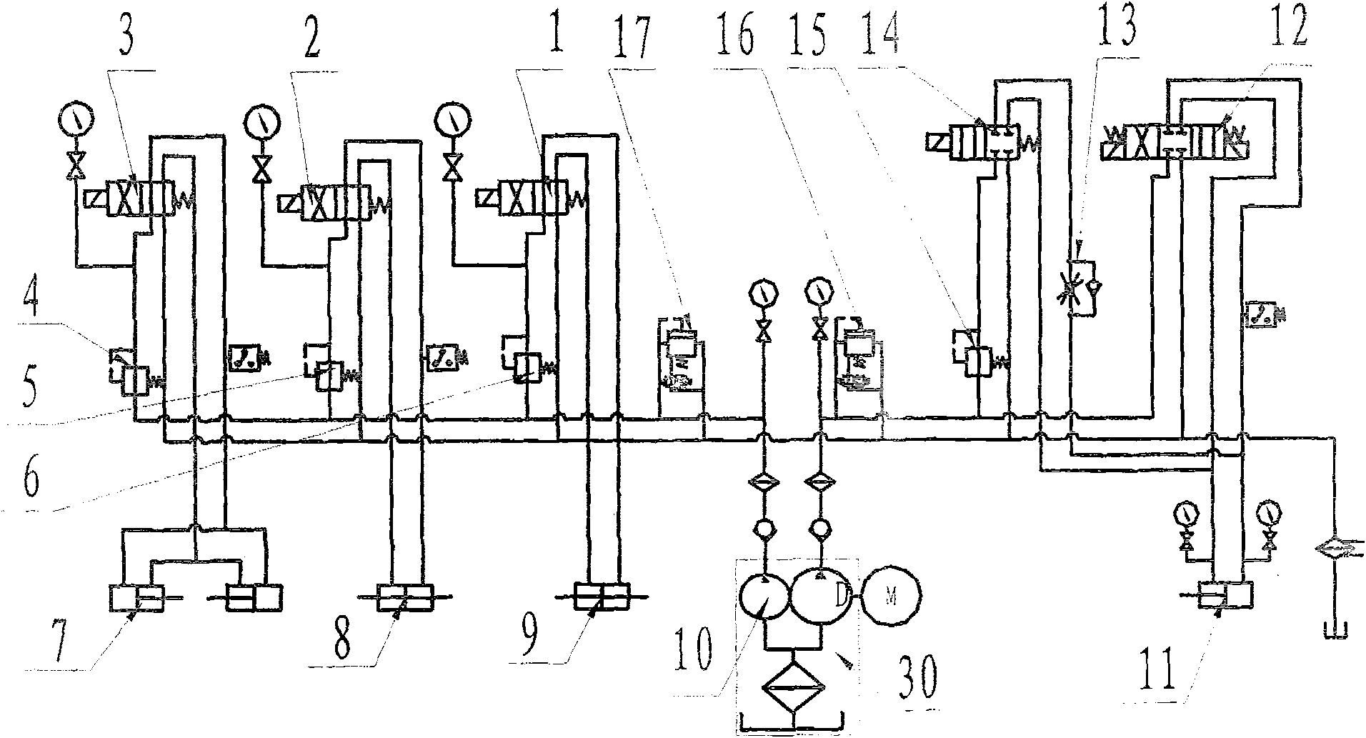
technical field [0001] The invention relates to a hydraulic control system of a friction welding machine. Background technique [0002] refer to figure 2 , the existing friction welding machine hydraulic control system includes a two-position four-way reversing valve, a pressure reducing valve, an oil cylinder, a three-position four-way reversing valve, a speed regulating valve, an electromagnetic overflow valve and a pump source device. Linkage to control the clamping and releasing, clutching and braking of the friction welding machine, as well as the direction, speed and axial pressure of the sliding table. [0003] The pump source device 30 of this hydraulic control system uses the double quantitative pump 10 to provide pressure oil for the system, wherein the small pump of the double quantitative pump 10 provides pressure oil for the clamping and clutch system, and the pressure is determined by the electromagnetic overflow valve B17 Control: the large pump of the doubl...

Claims


Application Information

Patent Timeline
Patent Type & Authority Patents(China)
IPC IPC(8): B23K20/12F15B11/02F15B11/17
Inventor 杜随更
Owner NORTHWESTERN POLYTECHNICAL UNIV
Learn More