
Gas diffusion layer for fuel cell and its production

A gas diffusion layer and fuel cell technology, which is applied to fuel cells, fuel cell parts, electrical components, etc., can solve problems such as narrow selection surface, and achieve the effect of improving electrode performance, simplifying production process, and strong operability.

Inactive Publication Date: 2009-07-29
DALIAN INST OF CHEM PHYSICS CHINESE ACAD OF SCI
View PDF5 Cites 2 Cited by
  • Summary
  • Abstract
  • Description
  • Claims
  • Application Information

AI Technical Summary

Problems solved by technology

However, the substances that can be used as hydrophobizing agents are still limited to the gases that can circulate in the reactor and contact the carbon particles in the vessel, or the substances that can be vaporized at relatively low temperatures, and the selection is extremely narrow.

Method used


Image

  • Gas diffusion layer for fuel cell and its production
  • Gas diffusion layer for fuel cell and its production
  • Gas diffusion layer for fuel cell and its production

Examples


Embodiment 1

[0028] Preparation of composite powder:

[0029] Take 3.0g of acetylene black, wet it with 6mL of isopropanol solution, add 90mL of deionized water, stir mechanically for 15min, and then perform ultrasonic treatment for 30min. Then, under mechanical stirring, slowly dropwise add 30g of 10wt.% PTFE emulsion, and stir well, so that the carbon black and PTFE are evenly mixed. Then place it in a 90°C water bath for coagulation, remove the clear liquid, and dry to prepare a PTFE / C composite precursor with a PTFE content of 50wt.%. Put this precursor into a microwave oven (700W, 2450MHz), and perform a heating procedure of microwave heating for 5s and stopping for 20s to remove residual water in the sample. Subsequently, the heating procedure of heating for 10s and stopping for 60s was repeated until the PTFE content was 30wt%. The obtained PTFE / AB composite powder with PTFE content of 30wt% is denoted as 30PTFE / AB.

[0030] Preparation of the gas diffusion layer:

[0031] Take ...

Embodiment 2

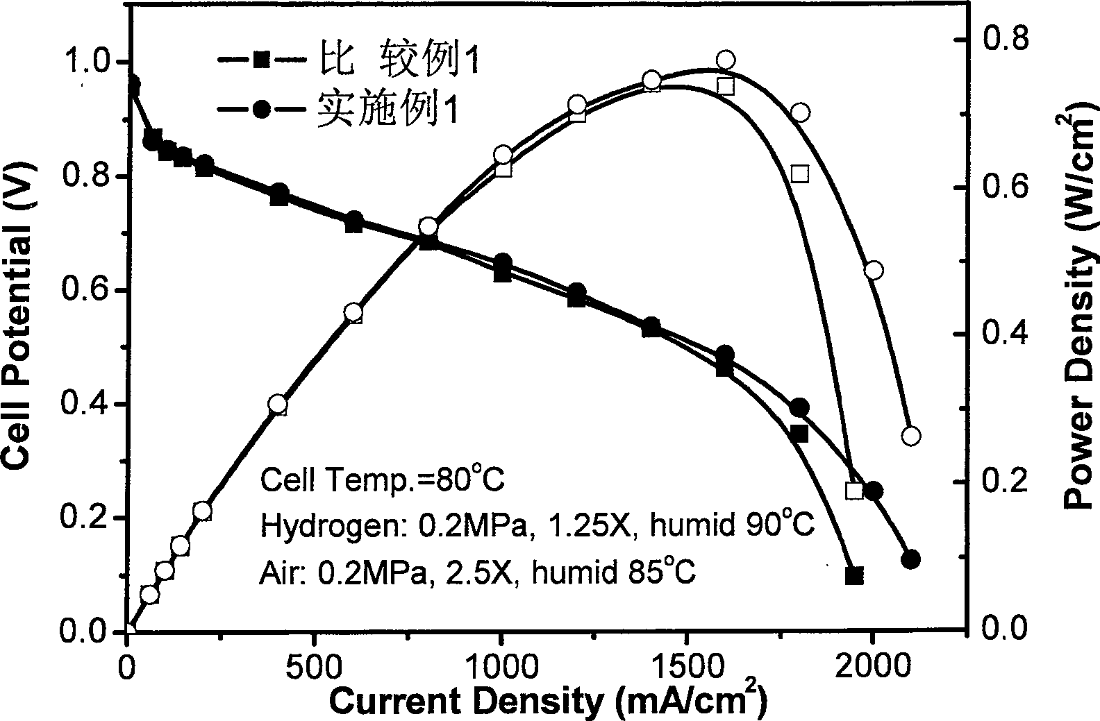
[0034] The 30PTFE / AB composite powder and the gas diffusion layer were prepared according to Example 1, except that the gas diffusion layer after scraping the microporous layer was dried naturally, and the battery could be assembled without roasting. Battery performance curve see Figure 4

Embodiment 3

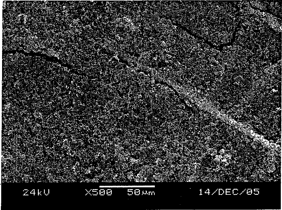
[0036] Take 3.0g VulcanXC-72 conductive carbon black, prepare 30PTFE / VX composite powder according to the method of Example 1. Its SEM photos are from the attached figure 1 visible in .

[0037] Preparation of the gas diffusion layer:

[0038] Take 3.57mg of 30PTFE / VX composite powder, and prepare a microporous layer on one side of the hydrophobic carbon cloth by dry scraping, with a carbon powder load of 0.05mg / cm 2 , the PTFE content of the carbon paper is 60wt.%. Then place it in a roasting furnace, heat at 240°C for 40 minutes, and bake at 340°C for 40 minutes. A single cell was assembled according to the method of Example 1.


PUM

PropertyMeasurementUnit
particle diameteraaaaaaaaaa
thicknessaaaaaaaaaa

Abstract

The invention relates to a fuel battery, in particular to a gas diffusing layer and the preparation for the fuel battery; the gas diffusing layer consists of basic bottom layer and a micro-hole layer, which is made by fabricating the micro-hole constructed by a water repellent agent / a composite powder body of electric conduction copper material at one side or two sides of a porous electric conduction basic bottom processed by a hydrophobic water; the water repellent agent / the composite powder body of electric conduction copper material is made by a microwave dielectric heating technology; because of the favorable water repellent performance and the grain diameter structure therefore, the gas diffusing layer to be fabricated has a strong and even water repellent performance and a suitable hole structure, so that the favorable mass transfer capability of the gas diffusing layer can be assured. The fuel battery assembled by the invention can show a better battery output performance, and is particularly suitable to be used in the fuel battery where the air is used as oxidizer with a strong practicality value.

Description

technical field [0001] The invention relates to a fuel cell, specifically a gas diffusion layer material for a fuel cell, that is, a composite powder of hydrophobic agent / conductive carbon material, a gas diffusion layer using the material and a preparation method thereof. Background technique [0002] As a high-efficiency and environment-friendly power generation device, fuel cell has become a research and development hotspot in various countries in recent years. Its core component, the three-in-one membrane electrode (MEA), is usually prepared by a hot-pressing process from a gas diffusion layer, a catalytic layer and a proton exchange membrane. The gas diffusion layer is composed of a conductive porous material, which plays multiple functions such as collecting current, conducting gas and discharging water, and is one of the key components that affect the performance of the electrode. An ideal diffusion layer should meet three conditions: good drainage, good air permeabi...

Claims


Application Information

Patent Timeline
Patent Type & Authority Patents(China)
IPC IPC(8): H01M8/02H01M4/94H01M4/86H01M4/88H01M8/0241
CPCY02E60/50Y02P70/50
Inventor 张华民王晓丽田植群陈剑衣宝廉
Owner DALIAN INST OF CHEM PHYSICS CHINESE ACAD OF SCI
Learn More