
Small heat pipe and method for manufacturing the same

A manufacturing method and heat pipe technology, which are applied in cooling/ventilation/heating transformation, indirect heat exchangers, lighting and heating equipment, etc., can solve the problems of high cost, low yield, affecting the popularization and application of sintered small heat pipes, and achieve thermal conductivity. Fast speed, excellent performance, satisfying the effect of quality

Inactive Publication Date: 2008-01-16
嘉善华昇电子热传科技有限公司
View PDF9 Cites 0 Cited by
  • Summary
  • Abstract
  • Description
  • Claims
  • Application Information

AI Technical Summary

Problems solved by technology

At present, small heat pipes made of netting and grooved wool suction cores can no longer meet the requirements of electronic products for heat dissipation elements, and small heat pipes with sintered cores have the defects of low yield and high cost, which affects the promotion of sintered small heat pipes application

Method used


Image

  • Small heat pipe and method for manufacturing the same
  • Small heat pipe and method for manufacturing the same
  • Small heat pipe and method for manufacturing the same

Examples


Embodiment Construction

[0020] The present invention will be further described below in conjunction with accompanying drawing:

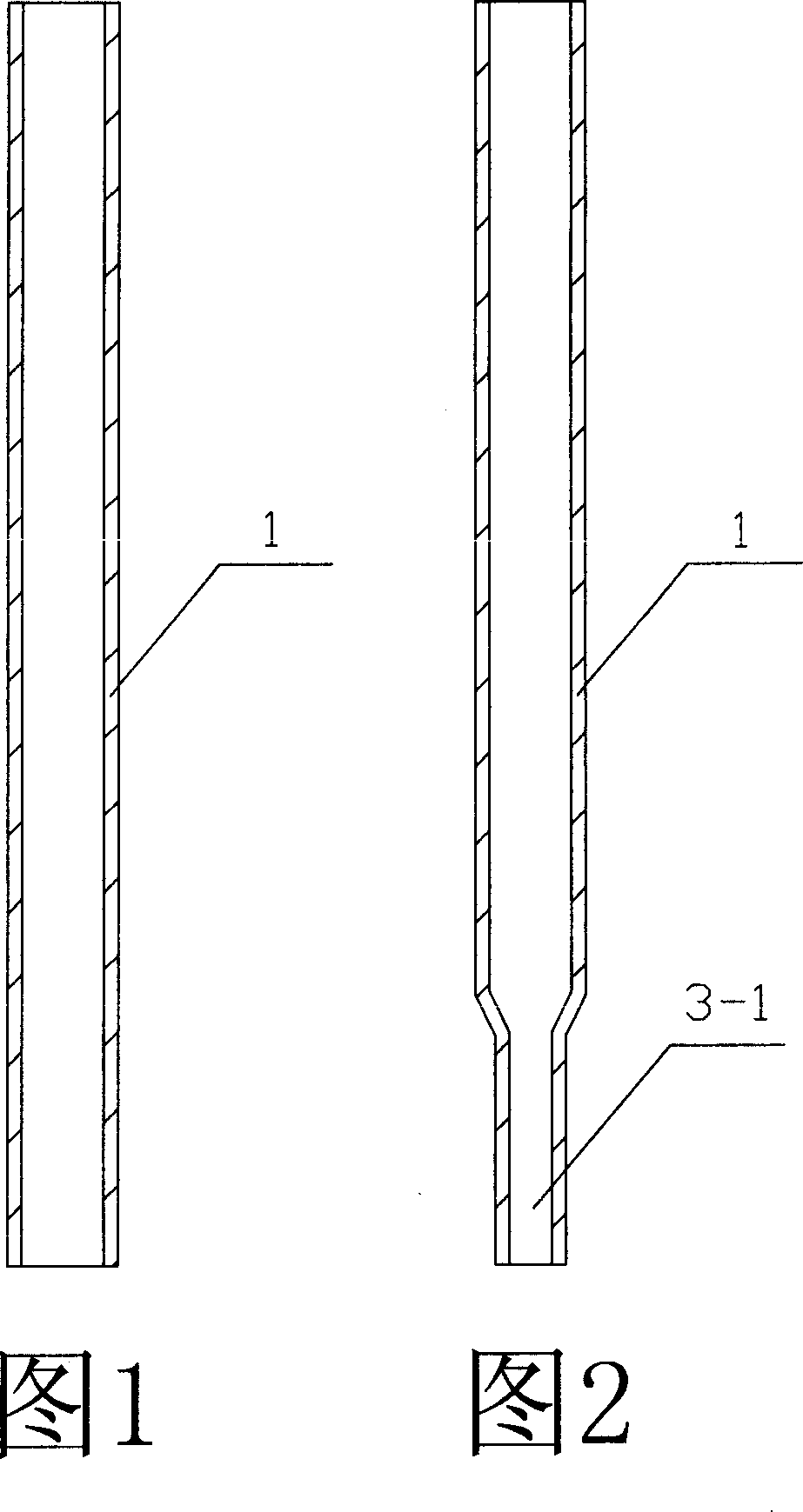
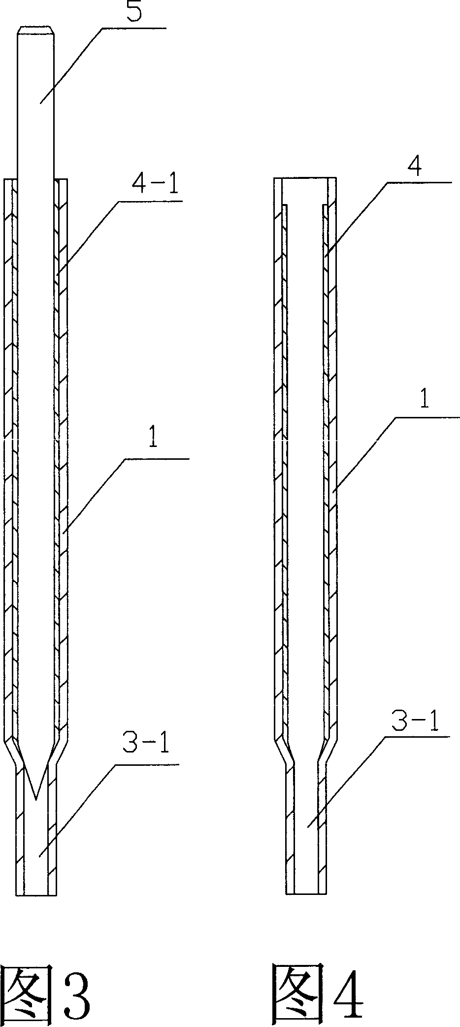
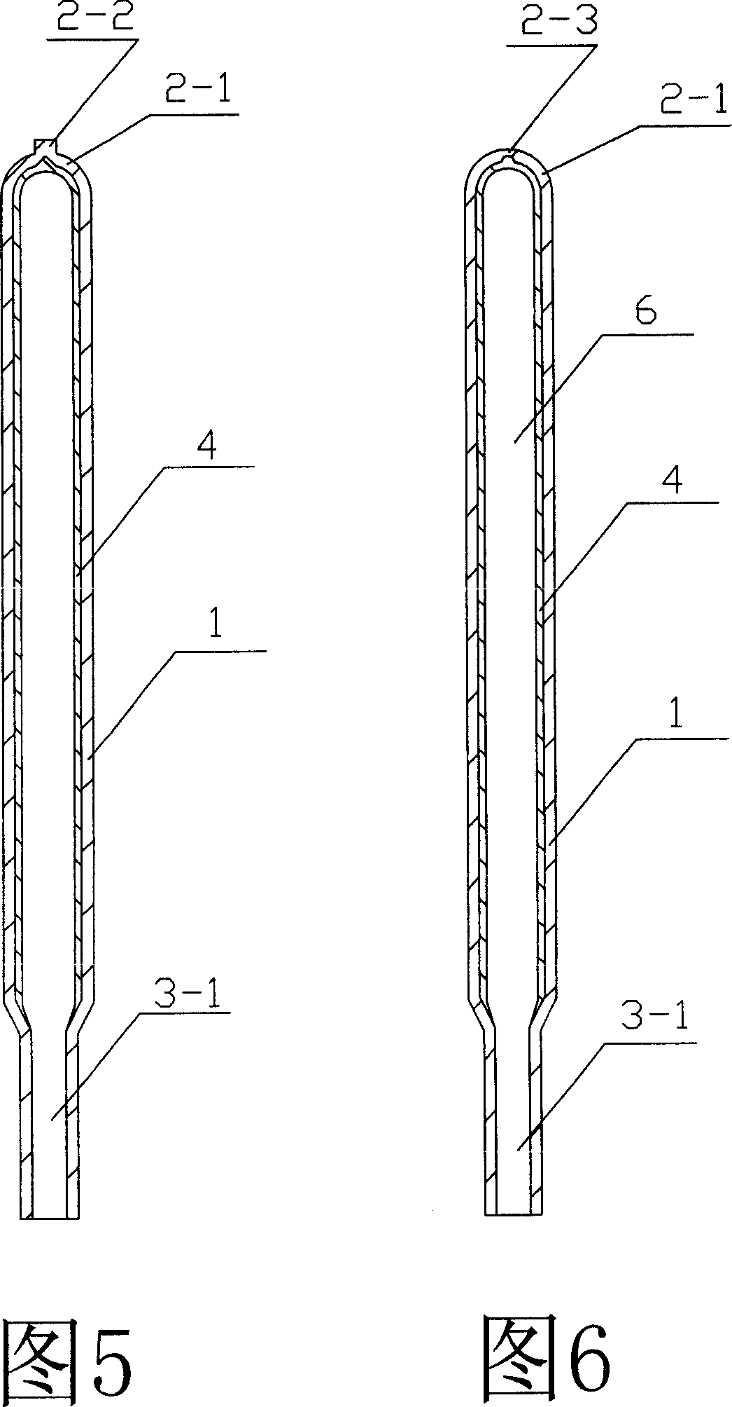
[0021] Referring to Fig. 7 and Fig. 8, this small heat pipe includes tail end 2, pipe body 1, sintered layer 4, and degassing end 3. The small heat pipe consists of tail end 2, pipe body 1, and degassing end 3 to form a sealed cavity 6. The interior is in a vacuum state; the tail end 2 of the tube body 1 is mechanically constricted and sealed by spot welding, and the degassing end 3 of the tube body 1 is squeezed into a degassing pipe 3-1 with a small diameter by mechanical blowing, and passes through the degassing pipe 3-1 Inject the working liquid into the sealed cavity 6, extract the air in the sealed cavity 6 through the degassing pipe 3-1, then pinch off the degassing pipe 3-1 and weld it in a sealed state; The upper sintering layer 4 has a certain thickness of porous capillary structure. The sintering layer 4 is sintered by a certain mesh of pure copper powder at high...


PUM


Abstract

This invention relates to a small heat pipe, which comprises tail end, pipe body, sinter layer and degassing end, wherein the tail end, pipe body and degassing end form the sealing cavity, and the inner wall of the pipe has a sinter layer; the sinter layer is absorbed working liquor. The method for manufacturing the heat pipe comprises the following steps: a) extruding one end of the pipe into a degassing pipe; b) inserting mandrel into the pipe, and the tapering of the mandrel must be inserted into the degassing pipe; c) filling metal powder into the gap between pipe inner wall and the mandrel; d) clinkering in high temperature to form sinter layer, cooling and getting the mandrel out; e) forming sealing tail end in the other end of the pipe; filling liquid heat-transfer agent, extracting air in the sealing cavity; f) grasping the degassing pipe, and then welding the end of the degassing pipe to form the degassing end.

Description

technical field [0001] The invention relates to a heat pipe and a manufacturing method thereof, in particular to a manufacturing method of a small heat pipe used for heat dissipation of heating electronic components (including a personal computer CPU). Background technique [0002] With the development and miniaturization of electronic products such as computers, communications, and photoelectric lighting LEDs at an astonishing rate in the "Moore's Law (Moor's Law)" proportional series, the relative heat dissipation problems are also increasing. How to solve this heat dissipation problem in a limited space and ensure the normal operation of electronic products requires that cooling module manufacturers and related scientific research institutions around the world increase investment in scientific research, actively seek and develop new types of high-efficiency heat dissipation that can meet the development needs of next-generation electronic products components. [0003] A ...

Claims


Application Information

Patent Timeline
Patent Type & Authority Patents(China)
IPC IPC(8): F28D15/02H05K7/20
Inventor 仝爱星杨互助王占篱
Owner 嘉善华昇电子热传科技有限公司
Learn More