Ceramic end mill and method for cutting difficult-to-cut material using the same

a technology of end mill and end mill, which is applied in the direction of metal-working equipment, workpieces, milling equipment, etc., can solve the problems of poor machining efficiency in usual cutting, difficult to improve productivity, and insufficient cutting ability of cutting tools

Active Publication Date: 2018-05-22
HITACHI TOOL ENG LTD
View PDF17 Cites 0 Cited by
  • Summary
  • Abstract
  • Description
  • Claims
  • Application Information

AI Technical Summary

Benefits of technology

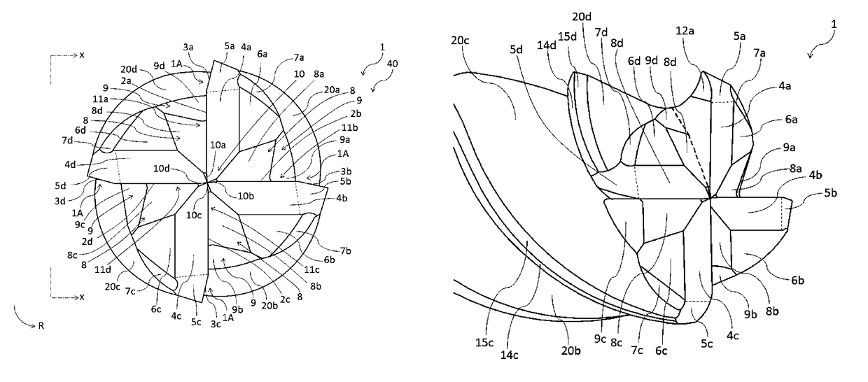
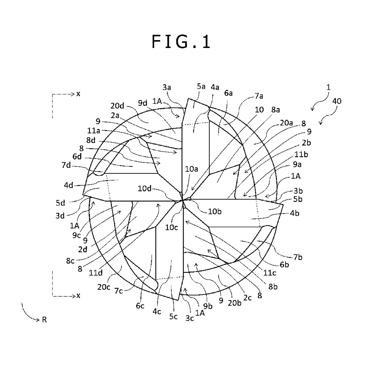
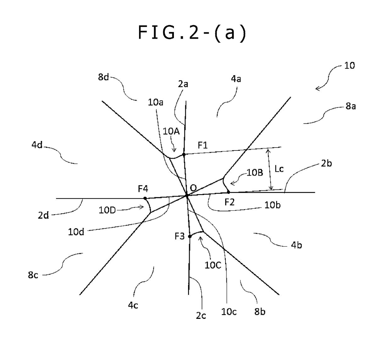
[0045]The respective cutting edges include the center cut edges and the end cutting edges continuous with the center cut edges. The center cut edges are disposed from the parts close to the rotation axis to the outer peripheral side in the radial direction and face the rotation axis. The end cutting edge second surfaces are positioned on the rear sides of the center cut edges and the end cutting edges in the rotation direction. The end cutting edge second surfaces are continuous with the positions facing the rotation axis or the positions approaching the rotation axis. The center grooves are formed between the end cutting edge second surfaces and the center cut edges on the rear side in the rotation direction. The center grooves pass on the rotation axis and partition the end cutting edge second surfaces with the center cut edges. This allows the center cut edges to be formed so as to face the center grooves passing on the rotation axis at the parts close to the rotation axis on the tool end surface. This ensures providing the end mill with the cutting ability continuously from the rotation axis to the outer peripheral side in the radial direction on the end surface on the cutting side.
[0046]Consequently, the end mill has the ability to uniformly cut the work material by the entire tool end surface. Therefore, while the end mill has the configuration equivalent to the cutting edge portion of the tool with the core, the end mill can secure an ability of handling the thrust process and the helical process, which ensure the cutting in the center portion.

Problems solved by technology

Since a beat-resistant alloy, such as a Ti alloy and a stainless steel, which is excellent in heat resistance and lightweightness and therefore is often used as a material for a mold and a component, is a difficult-to-cut material, machining efficiency is poor in usual cutting, making it difficult to improve productivity.
However, even if the performance is provided to the material itself, cutting ability as the cutting tool fails to be sufficiently exerted is some cases.
Accordingly, the end mill is not suitable for a thrust process where the toot axially advances and a helical process where the tool spirally cuts in the work material in principle.

Method used


Image

  • Ceramic end mill and method for cutting difficult-to-cut material using the same
  • Ceramic end mill and method for cutting difficult-to-cut material using the same
  • Ceramic end mill and method for cutting difficult-to-cut material using the same

Examples


working example

[0081]The following shows results of comparisons between the end mill 60 as Working Example 1 of the present invention that has the above-described requirements and end mills of Comparative Examples 1 and 2 that do not have the requirements of the present invention used for side surface working of a work material in Table 1. While the end mill 60 of the present invention contains a SiAlON-based ceramic as a base material, base materials of the end mills of Comparative Examples 1 and 2 are a cemented carbide, and a hard coating is performed on surfaces of the tools. Example of Present Invention 1 differs from Comparative Examples 1 and 2 in these points. Comparative Example 2 differs from Example of Present invention 1 and Comparative Example 1 in that the cutting velocity Vc is configured slow to avoid a high cutting temperature. The end mill 60 of Example of Present Invention 1 and the end mill of Comparative Example 1 performed the cutting under similar processing conditions. Mean...


PUM


Abstract

Ceramic end mill with cutting edge portion including gashes between cutting edges and adjacent in a rotation direction. Center cut edges are formed at end cutting edges close to and facing rotation axis O. Center grooves are formed on rear sides of center cut edges and end cutting edges in the rotation direction continuous with a radial direction. The center grooves are continuous with positions where end cutting edge second surfaces face or approach rotation axis O. End cutting edge second surfaces are laid between center cut edges and end cutting edges. Center grooves are formed between end cutting edge second surfaces and center cut edges positioned on a rear side of end cutting edge second surfaces in the rotation direction. The center grooves pass on rotation axis O. Center grooves double as rake faces of the respective center cut edges and are continuous with the gashes.

Description

CROSS-REFERENCE TO RELATED APPLICATIONS[0001]This application is a U.S. National Stage Application, which claims the benefit under 35 U.S.C. § 371 of PCT International Patent Application No. PCT / JP2015 / 079641, filed Oct. 21, 2015 which claims the foreign priority benefit under 35 U.S.C. § 119 of Japanese Patent Application No. 2014-219716, filed Oct. 28, 2014, and Japanese Patent Application No. 2015-108328, filed May 28, 2015, the contents of which are incorporated herein by reference.TECHNICAL FIELD[0002]The present invention relates to a radius type or a square type ceramic end mill that can cut a difficult-to-cut material such as a heat-resistant alloy at an ultrahigh speed and a method for cutting the difficult-to-cut material using the same.BACKGROUND ART[0003]Since a beat-resistant alloy, such as a Ti alloy and a stainless steel, which is excellent in heat resistance and lightweightness and therefore is often used as a material for a mold and a component, is a difficult-to-cu...

Claims


Application Information

Patent Timeline
Patent Type & Authority Patents(United States)
IPC IPC(8): B23C5/10B23C5/16
CPCB23C5/10B23C5/16B23C2228/24B23C2220/44B23C2226/18B23C2210/54B23C2210/045
Inventor SUEHARA, KANAME
Owner HITACHI TOOL ENG LTD
Why Eureka
Try Eureka