Low-torque choke valve for well automation

Inactive Publication Date: 2018-03-20
KARANI HANS
View PDF14 Cites 5 Cited by
  • Summary
  • Abstract
  • Description
  • Claims
  • Application Information

AI Technical Summary

Benefits of technology

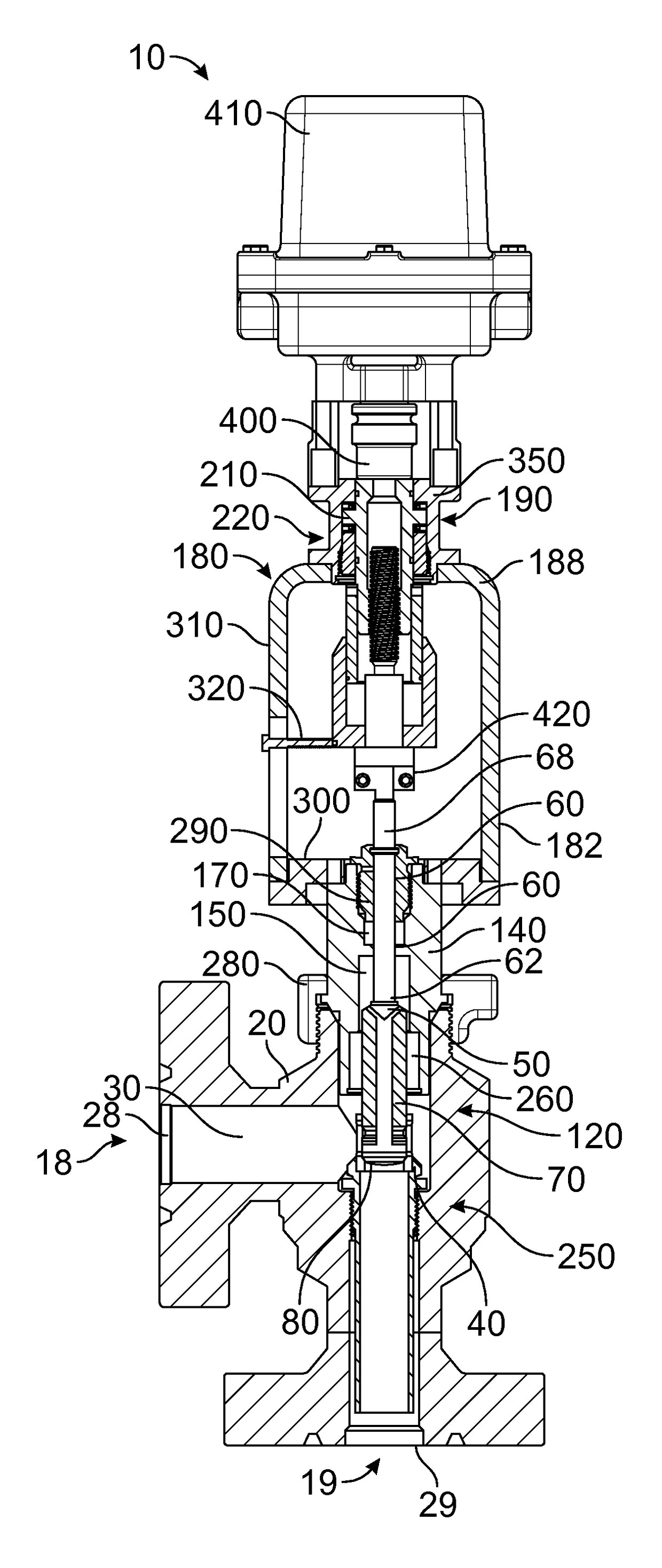
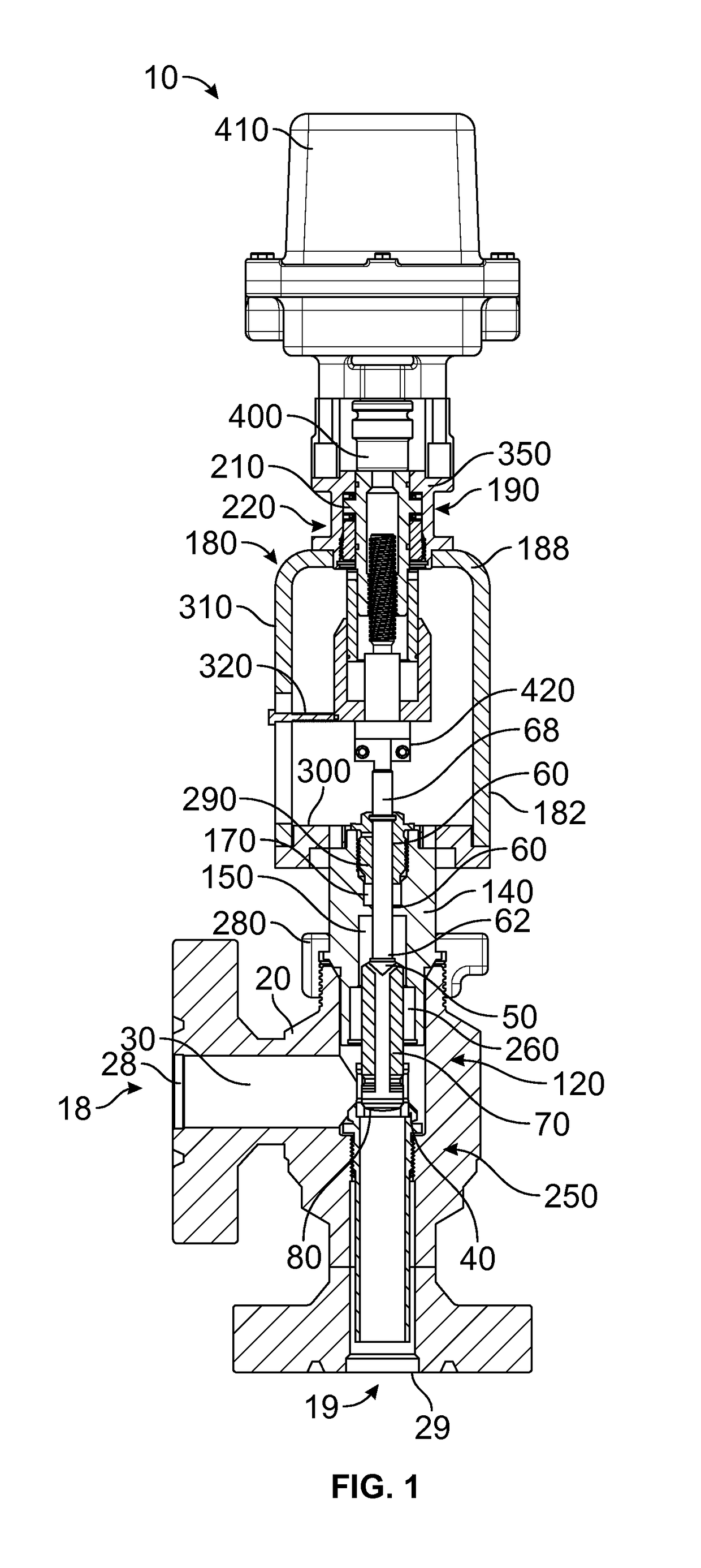
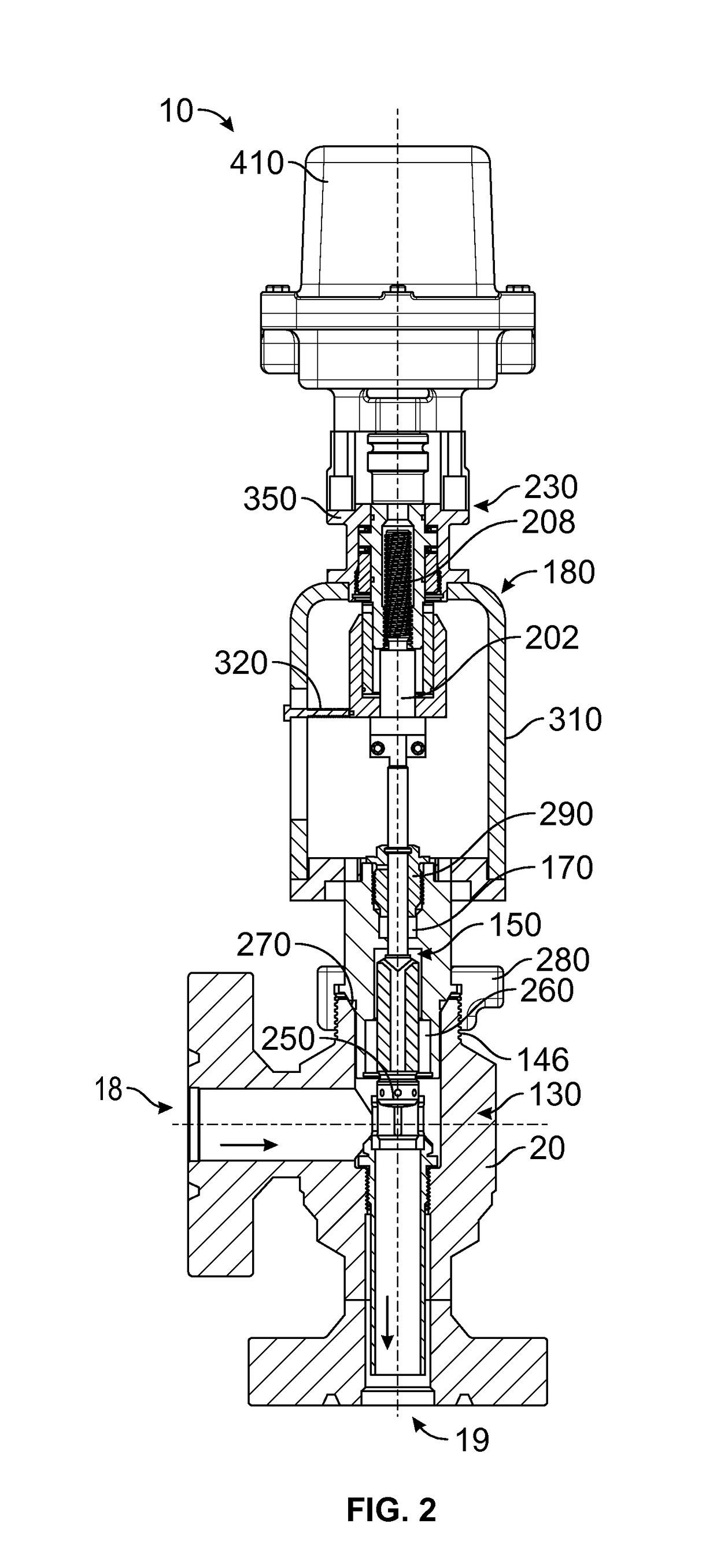
The present invention is a choke valve that is designed to prevent fluid flow when the valve is closed and allow for fluid flow when the valve is opened. It includes a breakaway actuator that disconnects the choke valve from the actuator motor in case of an over-torque situation. The valve's design has a metal-to-metal seal between the inlet and outlet, resulting in greater valve cavity volume, less fluid turbulence, and greater reliability and lower cost servicing. The valve's two-piece yoke design allows for easy separation of the actuator from the choke, making maintenance easier.

Problems solved by technology

Prior art choke valves, such as that taught in U.S. Pat. No. 5,706,856 to Lancaster on Jan. 13, 1998 and other prior art devices, particularly on fluid lines having 15,000 psi or greater, often have a relatively high torque requirement to open and close such valves, resulting in more energy demand and power consumption for remote, relatively large motorized actuators such as those found on motorized actuated chokes.
This is due primarily to lack of pressure balance between both sides of the choke and a relatively high seal friction (see FIG. 6 of Lancaster).
Such choke valves for use in product wells or oil and gasoline facilities result in higher operating costs.
Remote operation of new art choke valves of for oil production facilities, for example, results in low operating costs.
However, prior art valves, particularly on fluid lines having 15,000 psi or greater, often have a relatively high torque requirement to open and close such choke valves, resulting in more energy demand for remote, motorized actuators.
Such actuators typically have a high power requirement and cannot be easily set-up at remote locations far from utilities.
Further, prior art choke valves typically have multiple rubber seals (see FIG. 3 of Lancaster) that are susceptible to damage in oil producing and fracking operations due to high concentrations of CO2, H2S, and sand in many of the fluid flows resulting from such operations.
Moreover, such prior art valves have a relatively large number of seals contained in seal-cartridges that are difficult to remove from the bonnet due to the corrosive impact of sour gas and carbonic production fluids produced in oil and gas operations.
Of the entire bonnet must be replaced when servicing such valves, which is a costly repair.
Further, such prior art choke valves have seals that have little sealing value, but must still be maintained and serviced, which further increases seal friction and operating torque.
Such prior art indicator drive assemblies include a fabricated sleeve held in place with plastic buttons and pins that slide through the non-machined rough surface of the yoke, resulting often in misread indicator readings.
Field service and replacement of such indicators is difficult since the indicator mechanism is a part of the fixed connection of both the lower and upper stems and the assembly guide, and since it is locked by two large tapered nuts located at the upper and lower end of the tubing.
Such prior art devices provide no means of overload protection from higher motor drive torque due to use of fixed joints between the upper and lower stems (see FIGS. 1 and 5 of Lancaster).
Often such high torque requirement to open the choke valve increases the actuator motor's current capacity, thus damaging or burning out the motor, and causes thread damage upper and lower stems including the drive shaft assembly and coupling, which results a relatively high cost of repair and significant down time.
These three parts and the lower stem reduce volume within the body cavity and result in greater fluid turbulence, wear and tear within the body and the internal parts, which further increases required torque to move the valve as well as additional wear and tear on the internal components of such devices.
Further, such valves often result in the choke seat getting stuck into the chock body cavity due to corrosive activity at the seating area.
As such a valve seat utilizes an elastomer rubber seal, often such seal is worn prematurely and are destroyed internally.
As such, prior art valves of this type are often costly to service in the field and expensive to manufacture and assemble in the first place.
Lancaster and other prior art devices have further drawback that a single tubing structure holds the bonnet and upper hardware assembly, the indicator drive assembly and the upper and lower stems with a fixed coupling (see Lancaster FIGS. 1 and 5).
Such a one-piece design makes assembly, disassembly, and servicing complicated due to the difficulty of aligning the drive shaft, upper stem and lower stems.
Further, such a device results in the need for additional bearings and results in greater rotational friction.
Large tapered nuts at both ends of such tubing assembly are difficult to assemble, disassemble and service.
Moreover, the manual override assembly of the prior art devices requires a complicated handle and drive assembly to facilitate manual override of the valve (refer to Lancaster FIG. 4).

Method used


Image

  • Low-torque choke valve for well automation
  • Low-torque choke valve for well automation
  • Low-torque choke valve for well automation

Examples


example

[0057]A valve apparatus 10 identified as Prototype Choke AA200 Choke Assembly with a 4-20 mA electric Bettis-brand Actuator 410, as heretofore described, was tested for several days in August of 2013 at three different pressures (5000 psi, 10,000 psi, and 14,000 psi), cycling the valve a minimum of 160 times under pressure. The valve apparatus 10 was initially cycled 50 times at 5,000 psi, and resulting in a required 10.7 ft-lbs of torque to close the valve, and 5.3 ft-lbs to open the valve apparatus 10. Next, a room temperature of 86-degrees F., at a pressure of 10,500 psi, the torque required to close the valve apparatus 10 was 17.0 ft-lbs, and to open the valve apparatus 10 required 9.0 ft-lbs. Then, at a pressure of 14,000 psi, the torque required to close the valve apparatus 10 was 23.3 ft-lbs, and to open the valve apparatus 10 required 11.2 ft-lbs. All test checked good with no leaks. The valve apparatus 10 was cycled a total of 270 times with pressures up to 14,000 psi. In o...


PUM


Abstract

A choke valve body of a valve apparatus includes a lower stem that terminating at a lower end thereof with a plug. A conduit traverses a lower portion of the lower stem between at least one plug aperture traversing the plug to at least one top aperture traversing an upper end of the lower portion. The lower portion is slidably retained within the valve chamber between closed and open positions. A bonnet fixed with the valve body has a bonnet chamber for receiving the lower portion, and a bore with at least one annular seal for slidably retaining an upper portion. A yoke assembly is fixed with the bonnet, terminates at an upper end with a drive mechanism, and includes an upper stem with a threaded upper end that is driven between raised and lowered positions by the drive mechanism, the upper stem fixed with the lower stem.

Description

CROSS-REFERENCE TO RELATED APPLICATIONS[0001]This application claims the benefit of U.S. Provisional Patent Application 61 / 936,300, filed on Feb. 5, 2014, and incorporated herein by reference.STATEMENT REGARDING FEDERALLY SPONSORED RESEARCH AND DEVELOPMENT[0002]Not Applicable.FIELD OF THE INVENTION[0003]This invention relates to remote controlled actuated choke valves, and more particularly to an improved valve requiring very low operating torque or force, requiring less electric power consumption, and thus suitable to be automated by SCADA, RTU with HMI systems used in oil and gas well production.DISCUSSION OF RELATED ART[0004]Prior art choke valves, such as that taught in U.S. Pat. No. 5,706,856 to Lancaster on Jan. 13, 1998 and other prior art devices, particularly on fluid lines having 15,000 psi or greater, often have a relatively high torque requirement to open and close such valves, resulting in more energy demand and power consumption for remote, relatively large motorized a...

Claims


Application Information

Patent Timeline
IPC IPC(8): F16K3/26F16K3/24F16K3/314F16K37/00
CPCF16K3/314F16K3/246F16K37/0016Y10T137/8292Y10T137/8275F16K3/26
Inventor KARANI, HANS
Owner KARANI HANS
Why Eureka
Try Eureka