Plating apparatus

A coating device and coating technology, applied in hot-dip coating process, metal material coating process, coating, etc., can solve the problems of difficult maintenance equipment and expensive maintenance costs, and achieve the effect of preventing the wear of the rotating shaft

Inactive Publication Date: 2019-03-15
POHANG IRON & STEEL CO LTD
View PDF6 Cites 0 Cited by
  • Summary
  • Abstract
  • Description
  • Claims
  • Application Information

AI Technical Summary

Problems solved by technology

As a result, maintenance of equipment is difficult and expensive

Method used


Image

  • Plating apparatus
  • Plating apparatus
  • Plating apparatus

Examples


Embodiment Construction

[0035] In order to facilitate the understanding of the features of the present invention, the coating device of the embodiment of the present invention will be described in more detail below.

[0036] Components in the drawings attached to help understanding of the following embodiments are given reference numerals, and the same reference numerals are used for the same components in different drawings. In addition, in the description of the present invention, if it is considered that a specific description of related known structures or functions may obscure the gist of the present invention, the detailed description thereof will be omitted.

[0037] Next, specific embodiments of the present invention will be described with reference to the drawings.

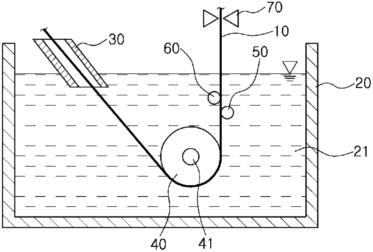
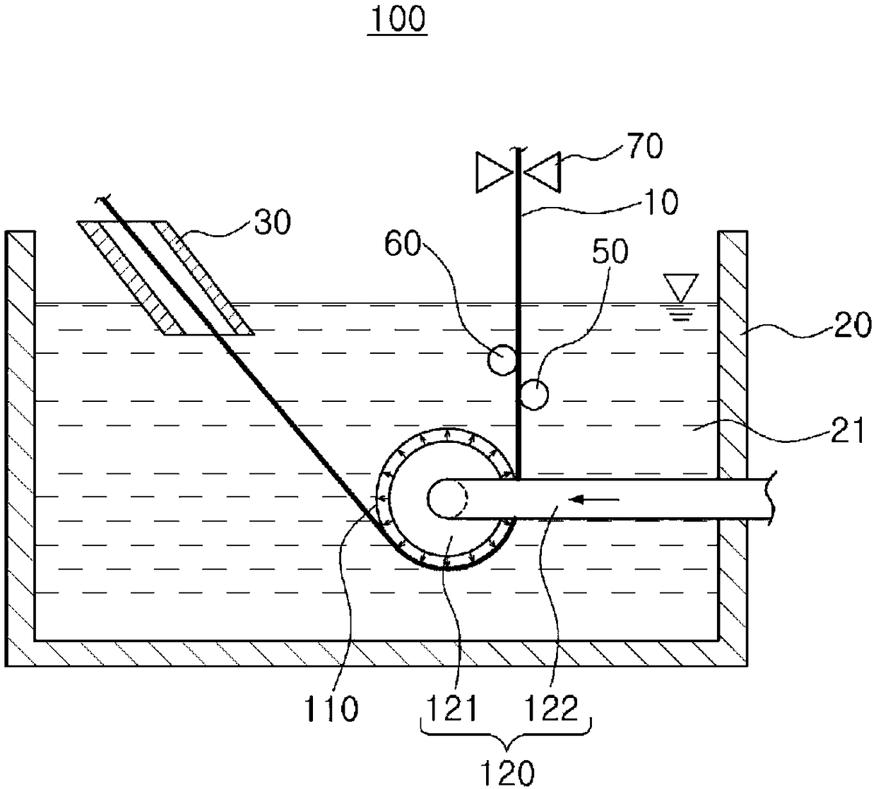
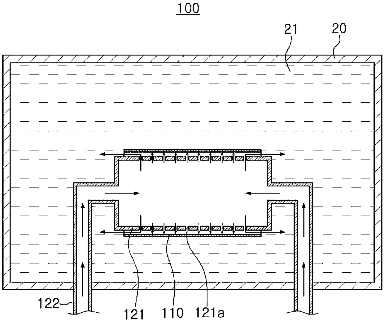
[0038] figure 2 and image 3 It is a front cross-sectional view and a plane cross-sectional view schematically showing a plating apparatus according to an embodiment of the present invention.

[0039] refer to figure 2 and...


PUM


Abstract

The present invention relates to a plating apparatus for supporting, in a noncontact manner, a rotating part for changing the proceeding direction of a steel sheet to be plated, and the plating apparatus comprises: a plating bath; the rotating part provided in a sleeve form, and disposed inside the plating bath so as to change the proceeding direction of the steel sheet to be plated; and a supportmeans disposed so as to pass through the center of the rotating part, and spraying gas, which is supplied therein, in the radial direction of the rotating part, not coming into contact with the rotating part, and rotatably supporting the rotating part. Therefore, since the rotating part can be rotatably supported in a noncontact manner, an effect of enabling problems, such as wear of a rotary shaft, bearing replacement, and heat generation caused by friction, to be prevented can be obtained.

Description

technical field [0001] The present invention relates to a coating device, and more specifically, to a coating device that supports a rotating portion for changing the traveling direction of a coated steel sheet in a non-contact manner. Background technique [0002] figure 1 is a front sectional view schematically showing a conventional plating device. [0003] refer to figure 1 , the cold-rolled steel plate coil continuously passes through an uncoiler (not shown) and a welding machine (not shown), and is heat-treated in a heating furnace (not shown), and the heated steel plate 10 is kept suitable for plating Into the coating bath 21 filled in the coating bath tank 20 under the state of the coating temperature. [0004] At this time, a protruding part 30 is connected between the heating furnace and the coating bath 20, and the inside of the coating bath 20 is equipped with a sinking roll 40 for changing the direction of the steel plate, a collecting roll 50 and a stabilizi...

Claims


Application Information

Patent Timeline
Patent Type & Authority Applications(China)
IPC IPC(8): C23C2/00C23C2/14C23C2/40
CPCC23C2/00C23C2/14C23C2/40C23C2/00344
Inventor 金气源宋龙燮韩仁硕宋吉镐
Owner POHANG IRON & STEEL CO LTD
Why Eureka
Try Eureka