Closure cap for the filler neck of a reservoir and filler neck therefor

Inactive Publication Date: 2011-03-01
REUTTER METALLWARENFABRIK GMBH
View PDF8 Cites 3 Cited by
  • Summary
  • Abstract
  • Description
  • Claims
  • Application Information

AI Technical Summary

Benefits of technology

[0004]The object of the present invention is therefore to provide a closure cap for the filler neck of a container of the type defined at the outset which prevents friction between the closure cap sealing ring and the sealing face of the filler neck regardless of the use by the user and which is embodied more simply.
[0017]The object of the present invention is therefore to provide a filler neck of a container of the type defined above that can be manufactured substantially more simply and thus considerably less expensively.
[0019]In a further advantageous feature, the underside of the closure base is a flat or plane annular-segmental face, and the filler neck, at least in the region of the neck opening and of the closure base, is a cast or molded part. These, which additionally leads to a further simplification of the filler neck, since the previously necessary sliding-block path can also be dispensed with, so that once again, a cast or molded part that need not be machined or needs only insignificant machining, can readily be used.

Problems solved by technology

Moreover, the spacer sleeve that must additionally be provided is complicated.

Method used


Image

  • Closure cap for the filler neck of a reservoir and filler neck therefor
  • Closure cap for the filler neck of a reservoir and filler neck therefor
  • Closure cap for the filler neck of a reservoir and filler neck therefor

Examples


Embodiment Construction

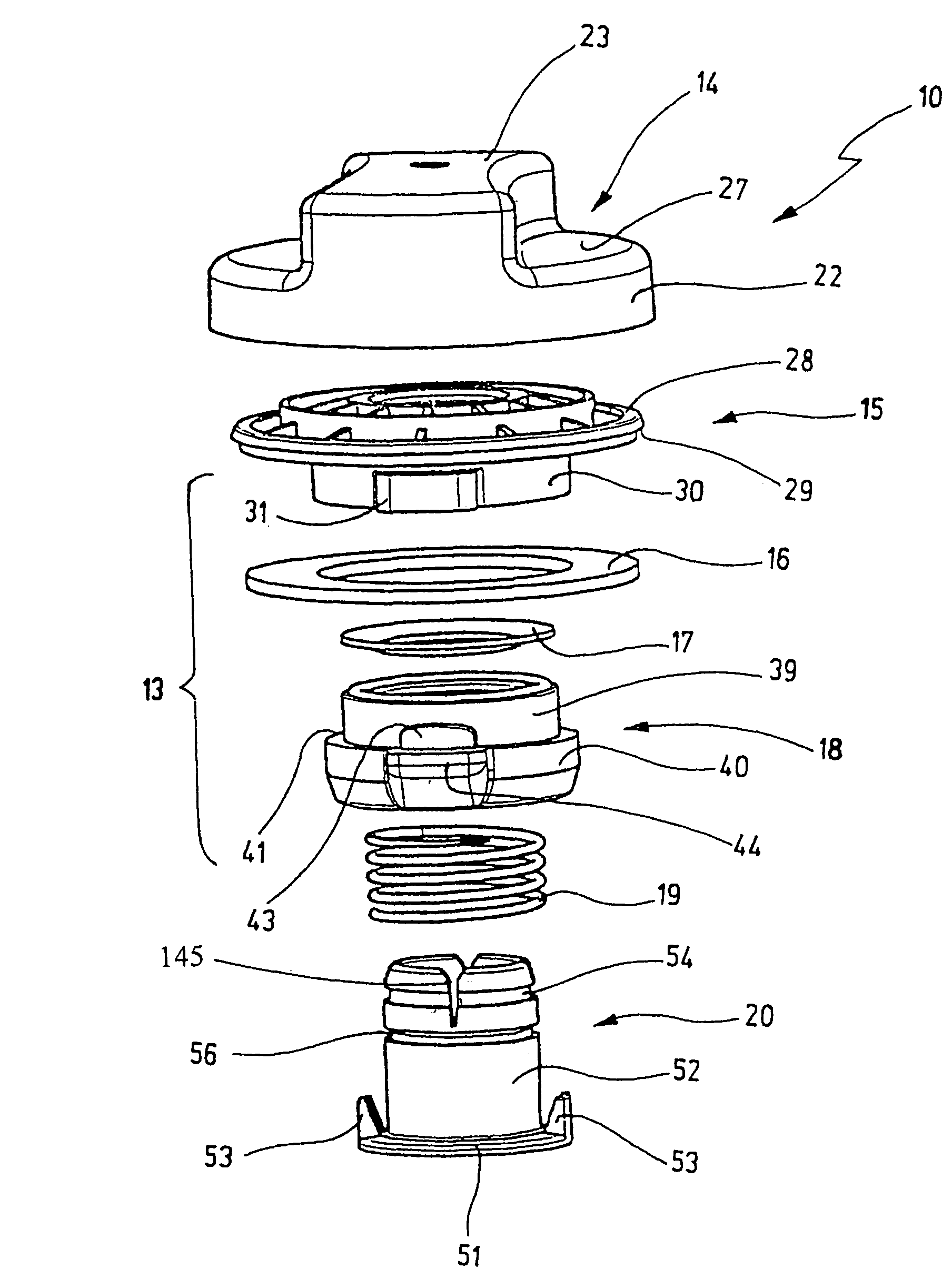
[0028]The closure cap 10 shown in the drawing serves the purpose of gas-tight, liquid-tight, and pressure-tight closure of a filler neck 11 of a container 12, in particular a fuel tank for motor vehicles, but also of a motor oil container for motor vehicles and for such containers in stationary systems.

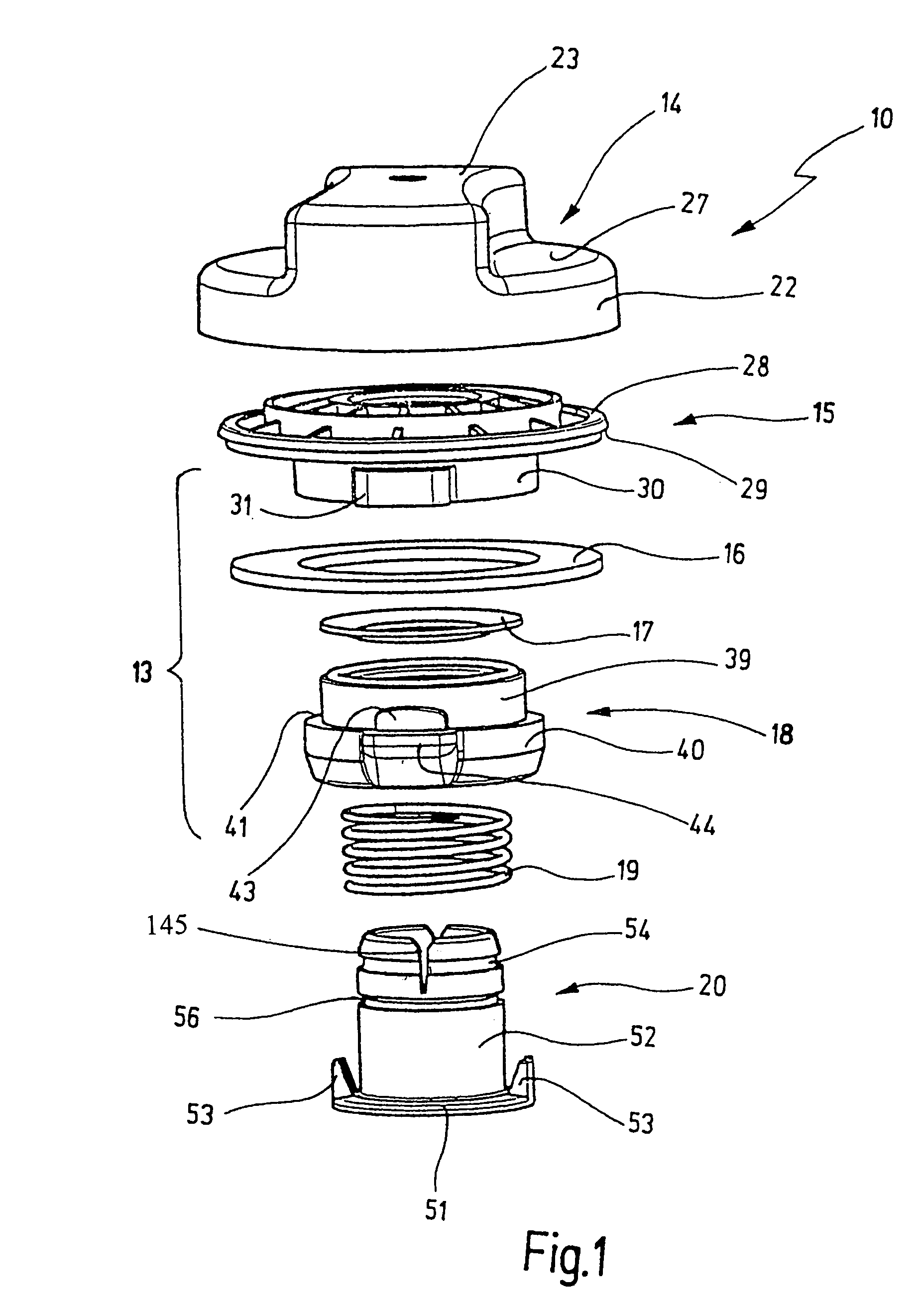
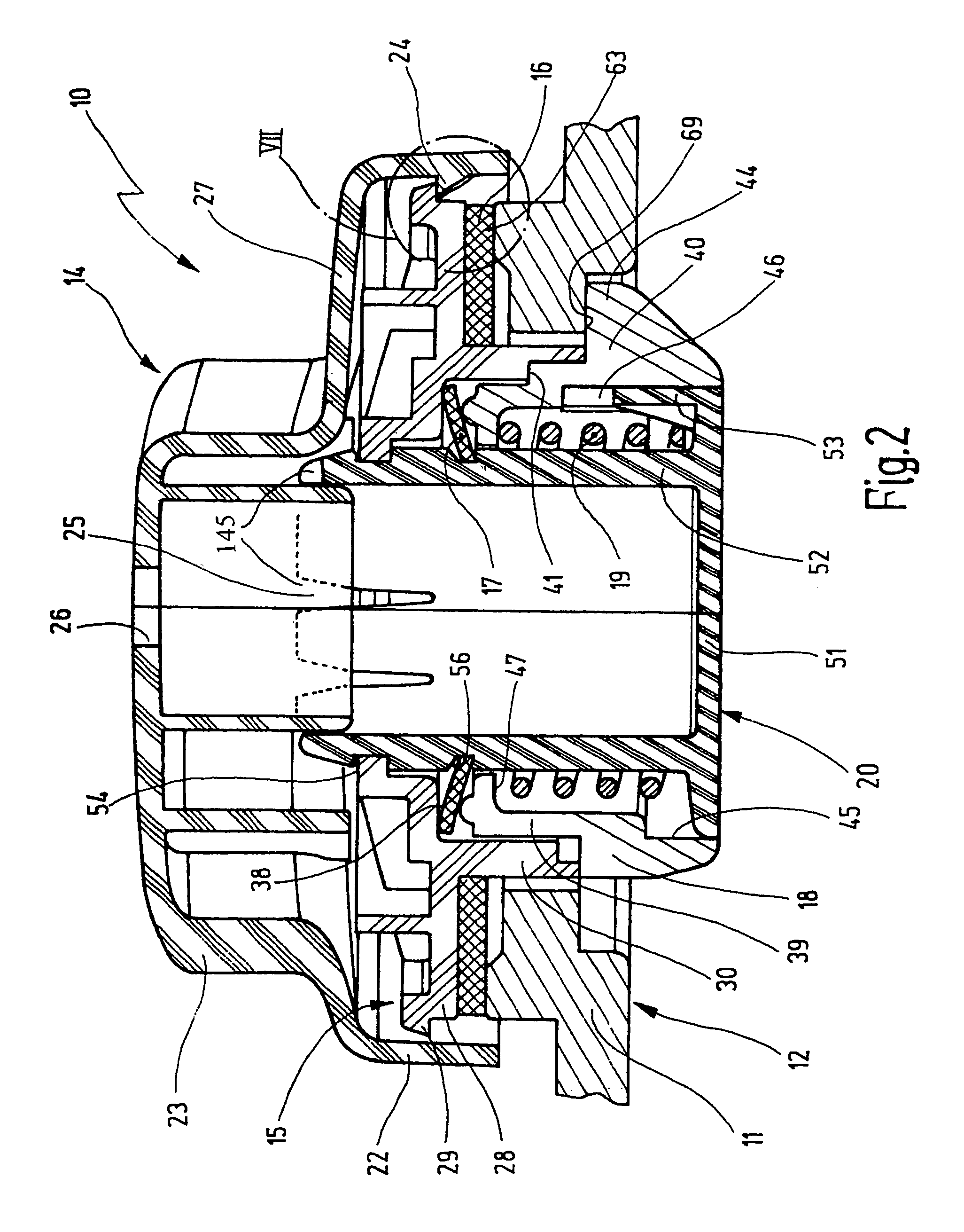
[0029]According to FIG. 1, the closure cap 10 essentially comprises a grip 14, a sealing part 15 with a sealing ring 16, a ring seal 17, a tightening part 18, a compression spring 19, and a shaft 20. In the assembled state, as is shown in FIG. 2, the shaft penetrates the compression spring 19 and the tightening part 18 and after that is equipped with the ring seal 17. The shaft 20 furthermore penetrates both the sealing ring 16 and the sealing part 15 that provided with the sealing ring 16, and the shaft is connected by its applicable end to the sealing part 15 in locking fashion, such that an axially fixed but circumferentially rotatable connection between the shaft 20 and the sealin...


PUM

PropertyMeasurementUnit
Fractionaaaaaaaaaa
Forceaaaaaaaaaa
Widthaaaaaaaaaa

Abstract

A closure cap for the filler neck of a reservoir, in particular, one for fuel or motor oil for e.g. motor vehicles, comprising a grip and a rotating lifting device whose first part (sealing part) facing the grip is provided with a sealing ring and whose other part (tightening part), which faces away from the grip and which is provided with detent lugs serving to engage under a closure cap of the filler neck, can be turned relative to the filler neck when the closure cap undergoes a turning motion. The other part (tightening part) can, when the grip undergoes a turning motion, be axially displaced relative to the first part (sealing part) of the rotating lifting device against the force of a spring. This axial displacement is such that, in the closed position of the closure cap on the filler neck of the sealing ring provided on the first part (sealing part), the tightening part is pressed against a sealing surface of the filler neck, and during the movement of the grip, an axial play exists between the sealing surfaces of the sealing ring and filler neck, whereby the first part (sealing part), with the axially acting sealing ring remains, when the closure cap undergoes a turning motion relative to the filler neck, unturnable with the filler neck by means of a turning closing connection.

Description

FIELD OF THE INVENTION[0001]The present invention relates to a closure cap for the filler neck of a container, in particular of a container for fuel or motor oil, for instance for motor vehicles.BACKGROUND OF THE INVENTION[0002]In one such closure cap, known from German Patent DE 30 05 419 C2, for a fuel tank, a grip is connected axially and in a manner fixed against relative rotation to one part (sealing part) via a coaxial closing tube, about which closing tube another part (tightening part) is retained axially movably, counter to the action of a spring, in the form of two diametrically opposed locking lugs. A spacer sleeve is disposed between the one part and the other part. The one part carries the sealing ring, which in the locked state of the closure cap rests sealingly on the sealing face of the filler neck.[0003]When this known closure cap, introduced into the filler neck, is manipulated, and upon locking or unlocking rotation relative to the filler neck, the closure cap is ...

Claims


Application Information

Patent Timeline
IPC IPC(8): B65D41/06B65D47/02B65D41/36B60K15/04
CPCB60K15/0406B60K2015/0451Y10S220/33
Inventor BEHNAMRAD, KAZEMRAULEDER, ROBERT
Owner REUTTER METALLWARENFABRIK GMBH
Why Eureka
Try Eureka