Tension-compression spring

Inactive Publication Date: 2009-02-12
RIVIN EVGENY
View PDF3 Cites 4 Cited by
  • Summary
  • Abstract
  • Description
  • Claims
  • Application Information

AI Technical Summary

Benefits of technology

[0010]The instant invention proposes a tension-compression spring in which the necessary displacements between interacting external and internal beveled rings are accommodated by internal shear in an elastomeric (rubber or rubber-like) layer or a layered (laminated) element comprising of alternating layers of elastomeric material and a rigid material, residing between the beveled surfaces of the external and internal rings, without sliding. Accordingly, friction between the contacting convex and concave tapered surfaces is totally eliminated.
[0011]Elimination of friction also eliminates the effect of “self-locking” of the spring. Since friction and lubrication are not anymore performance-influencing factors, the consistency of performance characteristics is improved. The disclosed spring is a “solid-state” device not requiring lubrication and a lubrication-delivering system, as well as not requiring sealing of the contact areas between the beveled surfaces of the rings in order to prevent their contamination.
[0013]In another embodiment of the proposed tension-compression spring, elastomeric layers or laminates are also placed between (and possibly attached to) upper and / or lower bases of the spring and supporting surfaces of the spring, thus preventing friction between the bases of the spring and the support surfaces.
[0014]In yet another embodiment of the proposed tension-compression spring, non-contacting surfaces of the ring are coated with a thin layer of the elastomeric material, thus protecting the rings from the environment, e.g. from humidity and from oxygen, the latter property preventing rusting of the spring surfaces. This approach would allow use of a less expensive metal for the tension-compression spring construction.

Problems solved by technology

Many commonly used springs, such as coil springs or slotted springs, do not comply with this requirement.
Thus, in both above described springs, significant parts of the spring material are loaded with stresses below their maximum stress, which results in greater size and weight of the spring as compared with cases when the material has stresses of more-or-less uniform magnitudes.
Some disadvantages of the design in FIG. 1 are as follows.
Also, sliding between surfaces 3, 4 would not start before the driving force in the contact is high enough to overcome static friction force in the contact, thus potentially resulting in a “jerky” behavior of the spring.

Method used


Image

  • Tension-compression spring
  • Tension-compression spring
  • Tension-compression spring

Examples


Embodiment Construction

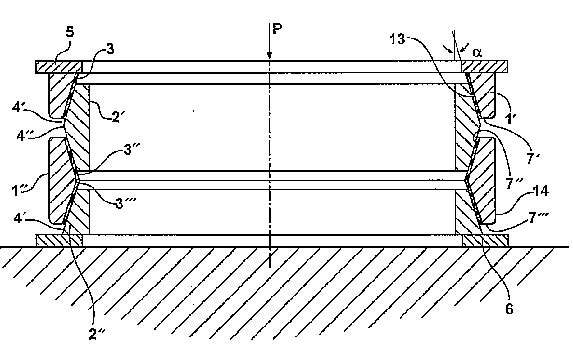
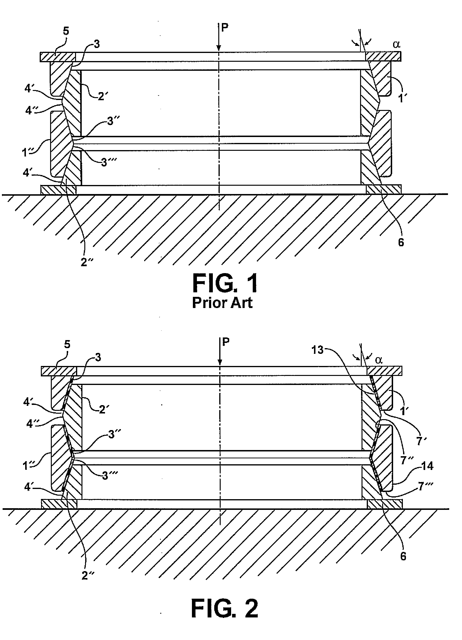
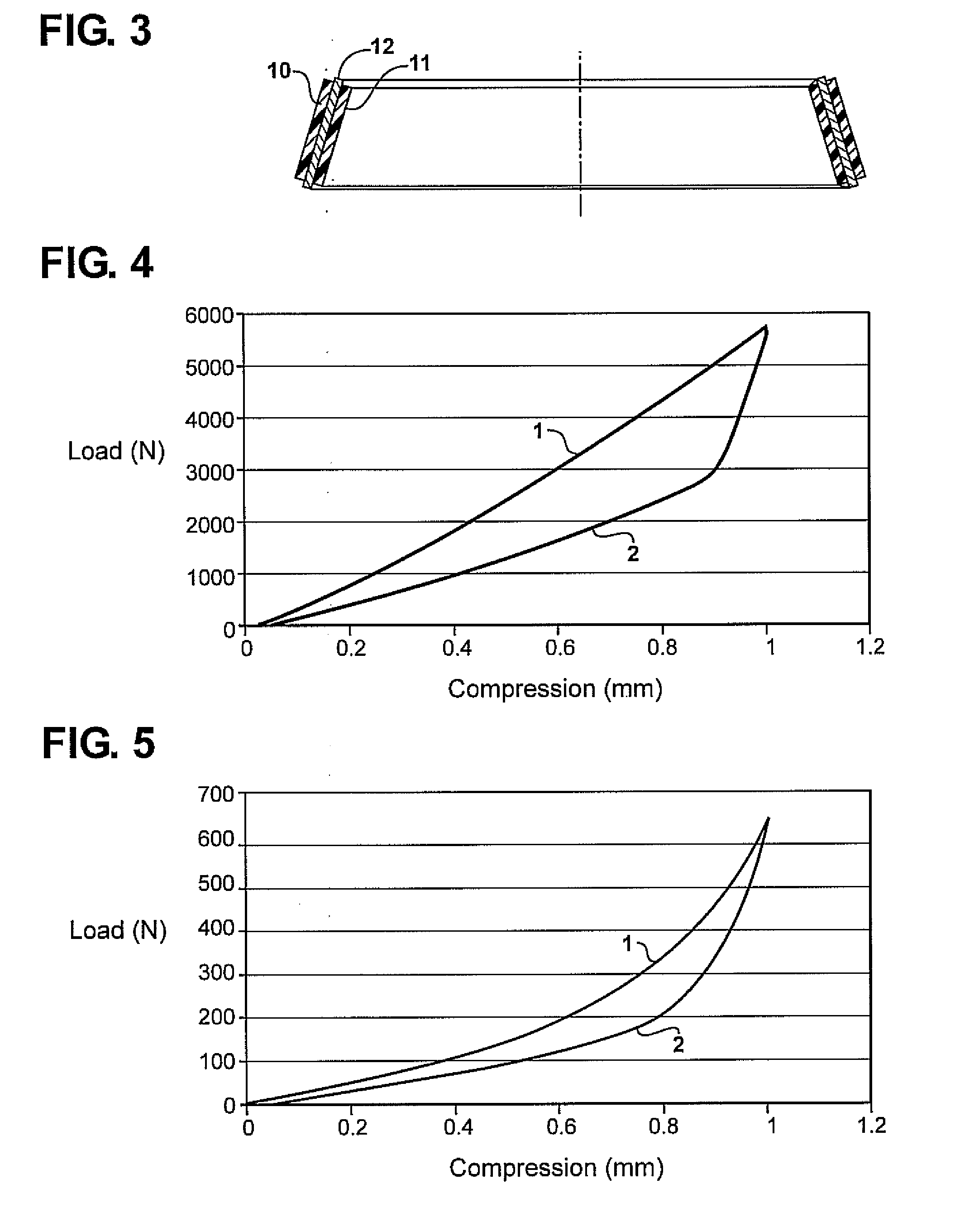
[0022]The following specification describes a tension-compression spring shown in FIG. 2 which is free from the shortcomings of the Prior Art tension-compression spring shown in FIG. 1. In FIG. 2, external (outer) rings 1 and internal (inner) rings 2 having conforming and interacting beveled surfaces 3 and 4, respectively, do not contact directly, but interact via layers of elastomeric (rubber or rubber-like) material or via multi-layered elastomer-rigid material (e.g., but not only, metal) laminates 7. In FIG. 2, single elastomeric layers 7 are shown. A cross section of a laminate 7′ comprising two elastomeric layers 10 and 11 bonded to intermediate rigid (e.g., but not necessarily, metal) layer 12 through a plane containing the axis of the spring is shown in FIG. 3. Layers of elastomeric layers or laminates 7 are attached (by bonding, by friction, or by other known techniques) to the beveled surfaces of internal rings 2′ and 2″ and / or of external rings 1′ and 1″.

[0023]When the axi...


PUM


Abstract

A tension-compression spring with high utilization of properties of the material from which the spring is fabricated wherein displacements between conforming and interacting beveled surfaces of rings constituting the spring are accommodated by internal shear in an elastomeric layer or layered (laminated) element residing between the conforming and interacting beveled surfaces of the rings.

Description

RELATED APPLICATION[0001]This application claims priority of U.S. Provisional Patent Application Ser. No. 60 / 959,730 filed Jul. 16, 2007, which is incorporated herein by reference.FIELD OF THE INVENTION[0002]The invention relates to mechanical design elements, such as springs.BACKGROUND OF THE INVENTION[0003]Springs are widely used mechanical components. In many mechanical devices, the size and weight of the springs are important characteristics which have to be minimized. Since the spring action is always associated with stressing / unstressing some elements, thus absorbing and releasing potential energy, the size / weight of a spring can be reduced if the stressed elements are uniformly stressed thus fully utilizing the capabilities of the spring material subjected to stress. Many commonly used springs, such as coil springs or slotted springs, do not comply with this requirement.[0004]In coil springs, the potential energy is largely stored by twisting (torsional deformation) of the wi...

Claims


Application Information

Patent Timeline
IPC IPC(8): F16F3/08
CPCF16F1/34
Inventor RIVIN, EVGENY
Owner RIVIN EVGENY
Why Eureka
Try Eureka