Topologies and methods for turbine engine start inverters

a technology of inverter and turbine engine, which is applied in the direction of engine starter, machine/engine, engine/propulsion engine ignition, etc., can solve the problems of low impedance to the start inverter, low ripple current from the engine start inverter, and engine generators typically not optimized for engine starting

Active Publication Date: 2017-12-12
HAMILTON SUNDSTRAND CORP
View PDF26 Cites 1 Cited by
  • Summary
  • Abstract
  • Description
  • Claims
  • Application Information

AI Technical Summary

Benefits of technology

[0007]In certain embodiments, the start inverter can include a plurality of three-level inverter phase legs. The peak current of the AC power can be substantially equivalent to the peak of the fundamental current of the AC power. It is contemplated that the AC power fundamental current flow can be substantially equivalent to the current rating for the start inverter, e.g., about 1 PU, thereby maximizing the torque provided by a starter-generator in motoring mode for the current rating.

Problems solved by technology

Because aircraft engine generators are designed mainly for operating in generating mode, the engine generator is typically not optimized for engine starting.
In general, sub-transient reactance associated with the starter generator may present low impedance to the start inverter and draw relatively high levels of ripple current from the engine start inverter.

Method used


Image

  • Topologies and methods for turbine engine start inverters
  • Topologies and methods for turbine engine start inverters
  • Topologies and methods for turbine engine start inverters

Examples


Embodiment Construction

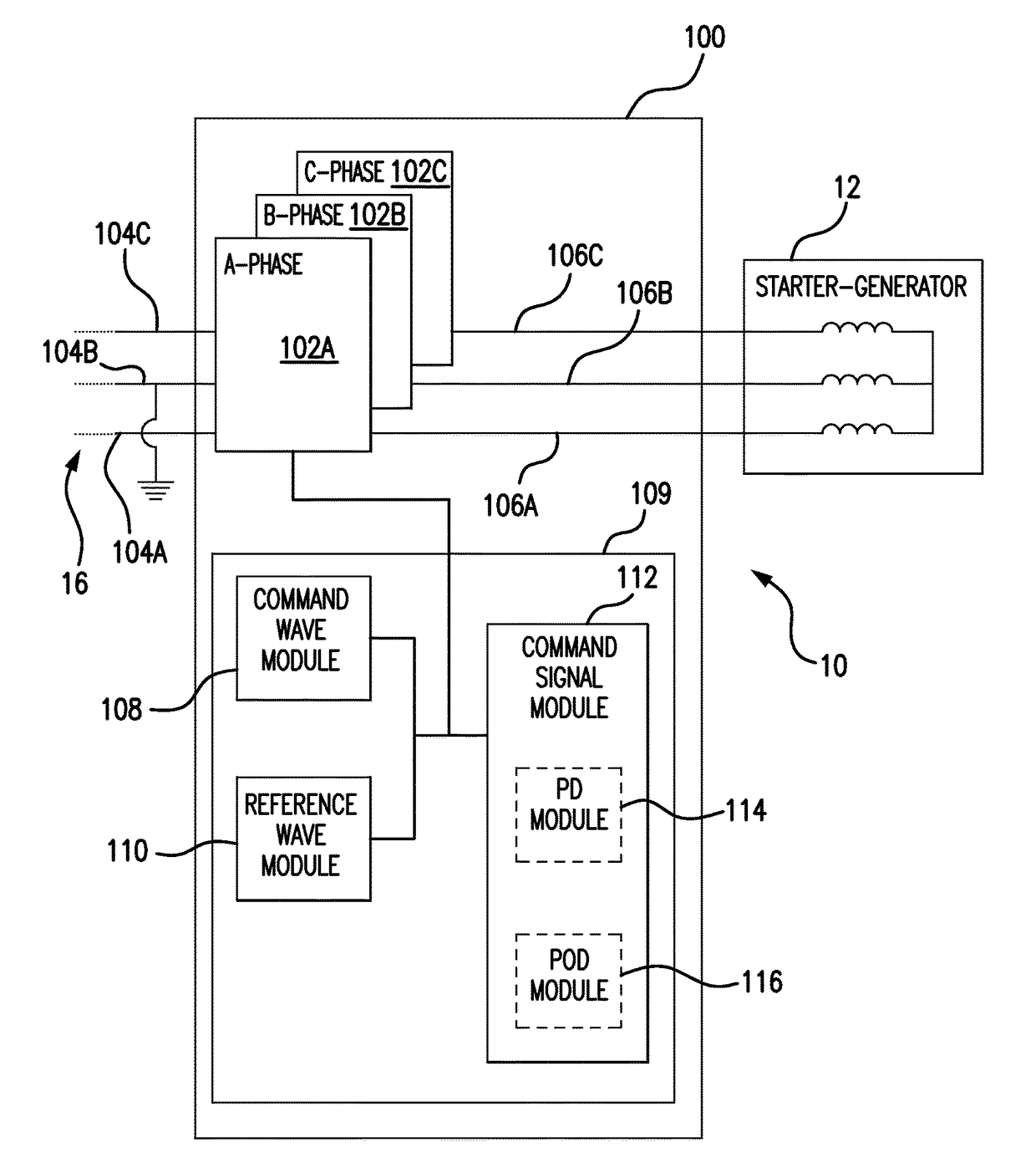
[0023]Reference will now be made to the drawings wherein like reference numerals identify similar structural features or aspects of the subject disclosure. For purposes of explanation and illustration, and not limitation, a partial view of an exemplary embodiment of a start inverter in accordance with the disclosure is shown in FIG. 3 and is designated generally by reference character 100. Other embodiments of start inverters and methods of providing power to starter generators for gas turbine engines in accordance with the disclosure, or aspects thereof, are provided in FIGS. 4-8, as will be described. The systems and methods described herein can be used to provide power to gas turbine engine starter-generators, such as in aircraft engines.

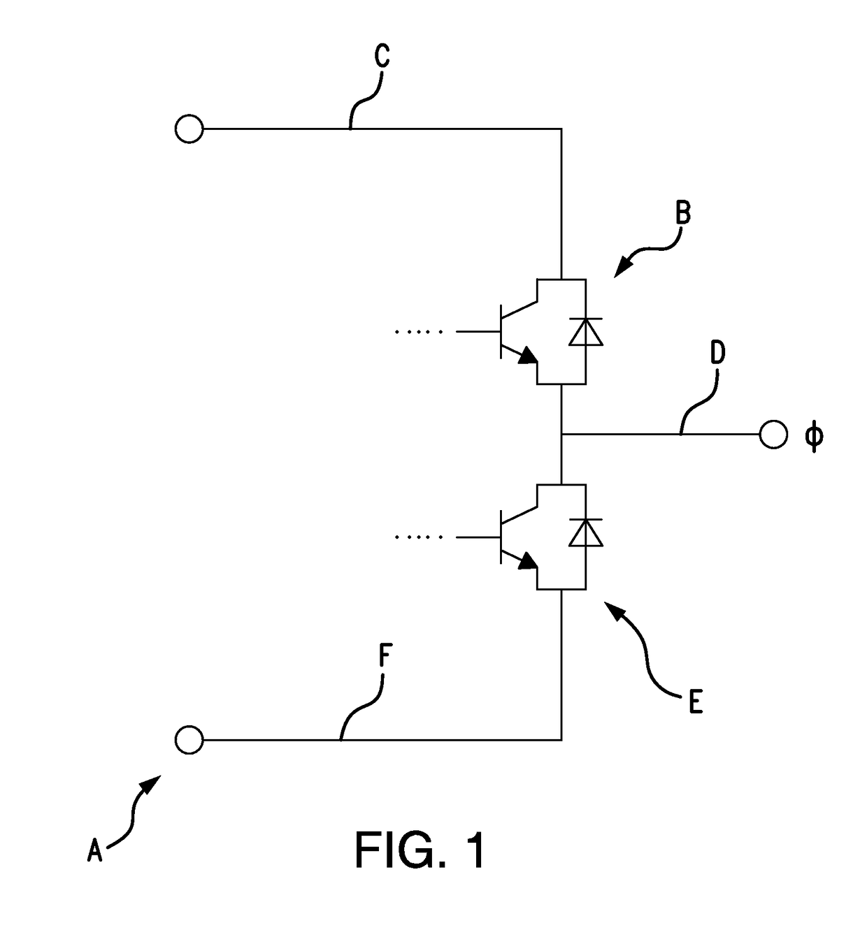
[0024]With reference to FIG. 1, a two-level inverter is generally referred to with reference letter A. Two-level inverter A includes a first solid-state switch device B arranged in series between a positive direct current (DC) power lead C and an...


PUM


Abstract

A start inverter for an electric engine start scheme includes an inverter phase leg with solid-state switches and a pulse width modulator operatively connected to the solid-state switches of the inverter phase leg. The pulse width modulator provides command signals to the solid-state switches of the inverter phase leg to invert direct current into alternating current with less ripple than a start inverter with two solid-state switches per phase leg.

Description

BACKGROUND OF THE INVENTION[0001]1. Field of the Invention[0002]The present disclosure relates to power conversion, and more particularly to start inverters for electric engine starters.[0003]2. Description of Related Art[0004]Aircraft engines are commonly started by non-electrical devices such as start turbines powered by compressed air. New generations of “More Electric” aircraft in recent years employ electric engine starters which operate the engine generator in a motoring mode powered using power provided by a start inverter. Because aircraft engine generators are designed mainly for operating in generating mode, the engine generator is typically not optimized for engine starting. In general, sub-transient reactance associated with the starter generator may present low impedance to the start inverter and draw relatively high levels of ripple current from the engine start inverter. Normally the solid-state switching devices, power capacitors, and other start inverter components ...

Claims


Application Information

Patent Timeline
Patent Type & Authority Patents(United States)
IPC IPC(8): F02C7/26H02M1/00H02M7/487H02M7/483H02M1/14H02P27/08
CPCF02C7/26H02M1/00H02M1/14H02M7/487H02P27/08H02M7/483F05D2260/85F01D15/10F02C7/275F05D2220/764F05D2220/762
Inventor CHAI, HARRY H.SAID, WALEED M.
Owner HAMILTON SUNDSTRAND CORP
Why Eureka
Try Eureka