
Resistance spot welding steel and aluminum workpieces with hot welding electrode at aluminum workpiece

a technology of resistive spot welding and hot welding electrode, which is applied in the direction of soldering apparatus, manufacturing tools, and welding devices. it can solve the problems of reducing the peel strength, and reducing the solidification of aluminum workpieces. it can facilitate the subsequent spot welding process, improve the solidification behavior of molten aluminum weld pools, and improve the thermal and electrical resistivity.

Active Publication Date: 2017-12-12
GM GLOBAL TECH OPERATIONS LLC
View PDF19 Cites 4 Cited by
  • Summary
  • Abstract
  • Description
  • Claims
  • Application Information

AI Technical Summary

Benefits of technology

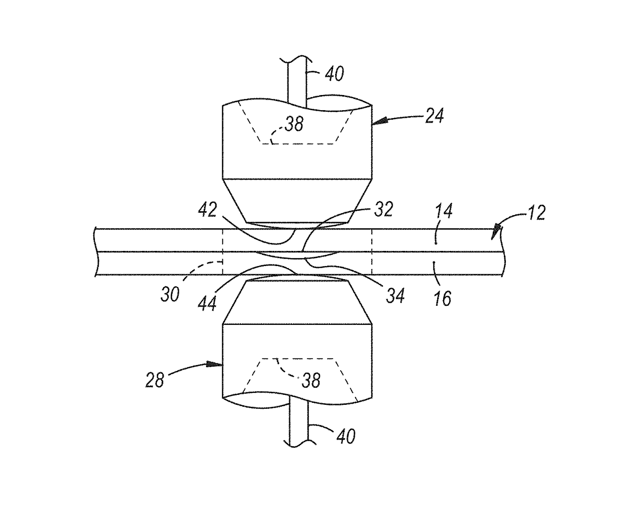
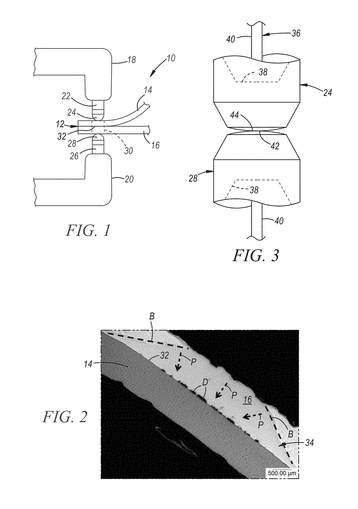
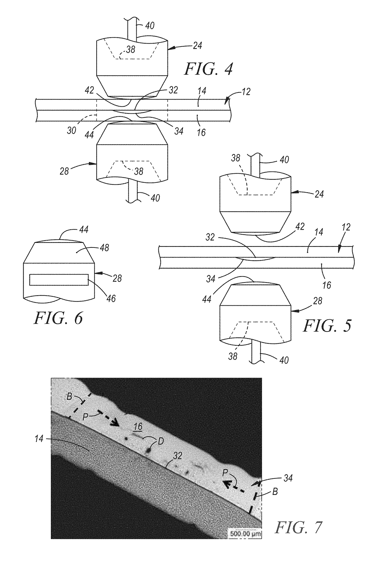
Two techniques for preheating the aluminum side welding electrode are described, which can be used to improve the spot welding process. The techniques involve either bring the electrodes into direct contact with each other or using a separate plate to pass electrical current. These techniques can heat the electrodes to high temperatures, which helps to introduce additional heat into the aluminum workpiece. This additional heat prevents defects and improves the strength and integrity of the weld joint. Overall, the patent text provides a simple solution to improve the quality of aluminum welds.

Problems solved by technology

Controlling the heat balance between the two metals so that a molten aluminum weld pool can be rapidly initiated and solidified in the aluminum workpiece can therefore be challenging.
It has been found, for example, that upon rapid cooling using standard industry practices, defects in the molten aluminum weld pool such as shrinkage voids, gas porosity, oxide residue, and micro-cracking are drawn toward and gather at the faying interface.
These two conditions have been shown to reduce the peel strength and weaken the overall integrity of the ultimately-formed weld joint.

Method used


Image

  • Resistance spot welding steel and aluminum workpieces with hot welding electrode at aluminum workpiece
  • Resistance spot welding steel and aluminum workpieces with hot welding electrode at aluminum workpiece
  • Resistance spot welding steel and aluminum workpieces with hot welding electrode at aluminum workpiece

Examples


Embodiment Construction

[0017]The methods and welding electrodes detailed in this description resolve several challenges encountered when resistance spot welding a workpiece stack-up that includes an aluminum workpiece and a steel workpiece. Though described in more detail below, in general the described methods and welding electrodes can alter the solidification behavior of a created molten aluminum weld pool and thereby limit or altogether preclude the accumulation of defects at the faying interface of the aluminum and steel workpieces. The methods and welding electrodes can also minimize the size and thickness of Fe—Al intermetallic layers formed at the faying interface. Of course, other improvements are possible. Taken together or alone, these measures help maintain suitable peel strength of the weld joint formed between the aluminum and steel workpieces, and help ensure the overall strength and integrity of the joint. And while the methods and welding electrodes are described below in the context of v...


PUM

PropertyMeasurementUnit
electrical conductivityaaaaaaaaaa
temperatureaaaaaaaaaa

Abstract

A method of resistance spot welding a steel workpiece to an aluminum or aluminum alloy workpiece involves providing a workpiece stack-up that includes a steel workpiece and an aluminum workpiece and preheating the welding electrode that is meant to contact the aluminum or aluminum alloy workpiece. The method further involves pressing the preheated welding electrode and another welding electrode against opposite sides of the workpiece stack-up, with the preheated welding electrode abutting the aluminum or aluminum alloy workpiece, and passing an electrical current between the two welding electrodes at a weld site to initiate and grow a molten weld pool within the aluminum or aluminum alloy workpiece.

Description

CROSS-REFERENCE TO RELATED APPLICATIONS[0001]This application claims the benefit of U.S. provisional patent application No. 61 / 880,564, filed on Sep. 20, 2013, the entire contents of which are hereby incorporated by reference.TECHNICAL FIELD[0002]The technical field of this disclosure relates generally to resistance spot welding and, more particularly, to resistance spot welding a steel workpiece to an aluminum or aluminum alloy workpiece.BACKGROUND[0003]Resistance spot welding is used in a number of industries to join together two or more metal workpieces. The automotive industry, for example, often uses resistance spot welding to join together pre-fabricated metal workpieces during the manufacture of a vehicle door, hood, trunk lid, or lift gate, among other vehicle parts. Multiple individual resistance spot welds are typically formed along a peripheral region of the metal workpieces or at some other bonding region to ensure the vehicle part is structurally sound. While spot weldi...

Claims


Application Information

Patent Timeline
Patent Type & Authority Patents(United States)
IPC IPC(8): B23K37/02B23K31/02B23K11/34B23K11/11B23K11/20B23K103/20
CPCB23K11/20B23K11/34B23K11/115B23K2203/20B23K2103/20
Inventor SCHROTH, JAMES G.SIGLER, DAVID R.PERRY, THOMAS A.
Owner GM GLOBAL TECH OPERATIONS LLC
Learn More