Terahertz wave phase difference measurement device

a phase difference measurement and phase difference technology, applied in measurement devices, optical radiation measurement, instruments, etc., can solve the problems of limited methods for generating and detecting a plurality of frequencies of terahertz waves, major problems arise, and the conventional terahertz wave technology does not have a high output terahertz wave oscillator or highly sensitive terahertz wave detector

Inactive Publication Date: 2017-12-05
HITACHI HIGH-TECH CORP
View PDF9 Cites 5 Cited by
  • Summary
  • Abstract
  • Description
  • Claims
  • Application Information

AI Technical Summary

Benefits of technology

[0025]The following is a brief description of effects obtained by a typical embodiment of the invention disclosed in the present application:
[0026]A high-sensitivity and high-accuracy terahertz wave phase difference measuring system can be provided. It is possible to provide a device which is capable of, based on detected phase difference information, detecting the thickness of a layer of a measured object, visualizing a surface shape and an internal structure, and measuring an index of refraction. Since measurements can be made regardless of the optical, path length of a terahertz wave, it is possible to measure a large-sized object and an object placed in an invisible case where a reflection position is unknown.

Problems solved by technology

However, the conventional terahertz wave technologies do not have a high output terahertz wave oscillator or a highly sensitive terahertz wave-detector and further methods for generating and detecting a plurality of frequencies of terahertz waves are limited.
For this reason, some major problems arise.
Practical measured objects are limited to thin films, such as painted films on paintings and works of art, foamed materials excellent in terahertz wave permeability, and the like and it takes a long time for measurements.
Because of these problems, it used to be difficult to introduce a terahertz wave technology into a product inspecting apparatus or the like requiring high-speed and high-accuracy measuring performance.

Method used


Image

  • Terahertz wave phase difference measurement device
  • Terahertz wave phase difference measurement device
  • Terahertz wave phase difference measurement device

Examples


Embodiment Construction

Typical Embodiment

[0033]Hereafter, a description will be given to an embodiment of the present invention with reference to the drawings. The device configuration and details of processing operation described below are just examples and any other embodiment can be implemented by combining or replacing this embodiment with an existing technology.

[0034]In this embodiment, a light source capable of generating near infrared light is used as a pump light source and a seed light source. Near infrared light generated by the pump light source is designated as pump light and near infrared light generated by the seed light source is designated as seed light.

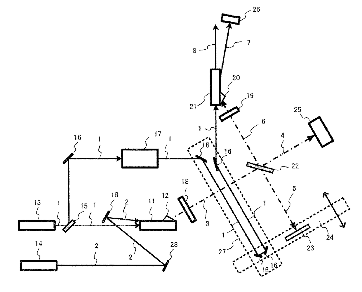
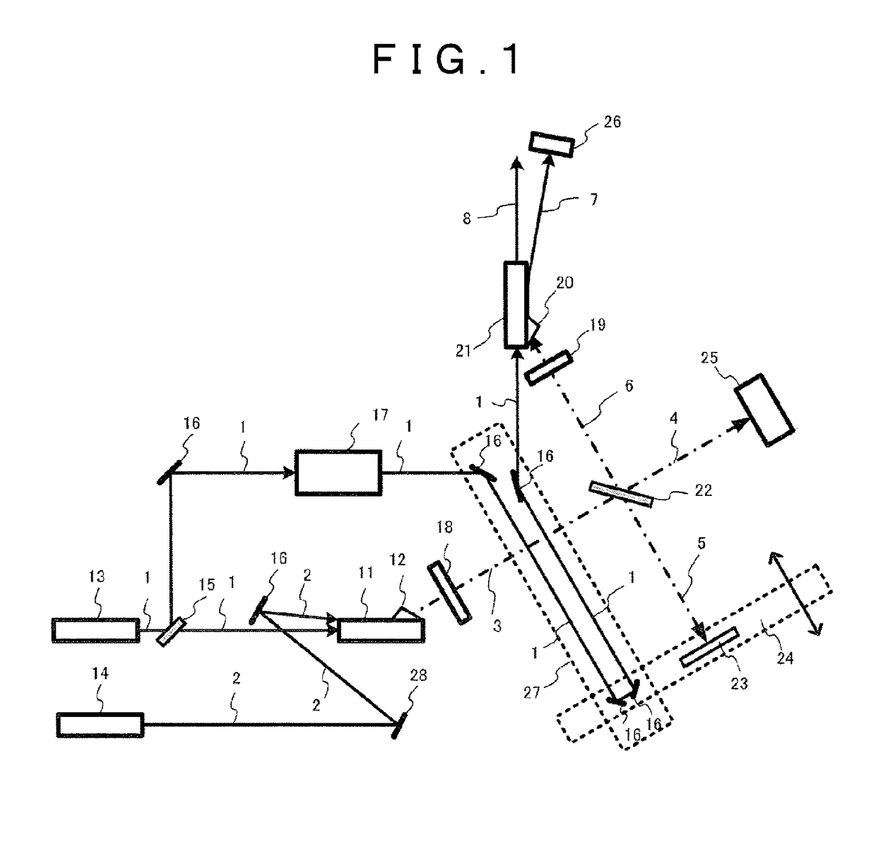
[0035]FIG. 1 illustrates a first exemplary configuration of a terahertz wave phase difference measuring system. Pump light 1 outputted from a pump light pulse laser light source 13 is bifurcated into two directions by a beam splitter 15. The pump light pulse laser light source need not be a single laser light source. In usual cases, an opti...


PUM

PropertyMeasurementUnit
frequencyaaaaaaaaaa
wave lengthaaaaaaaaaa

Abstract

In order to provide a high-sensitivity terahertz wave phase difference measurement system having a high S / N ratio, terahertz interference waves are observed using a half mirror and a movable reference mirror, and the phase difference is calculated, by a terahertz wave generation / detection device that obtains a high S / N ratio by employing a terahertz wave generator for irradiating a non-linear optical crystal with angular phase-matched pump light and seed light, and a terahertz wave detector for irradiating a non-linear optical crystal with angular phase-matched pump light and terahertz waves. In order to match the optical path length of the pump light and the terahertz waves irrespective of the position of the movable reference mirror and the position of a measured object, a first optical delay device, and a second optical delay device that operates in conjunction with movement of a movable reference mirror of a Michelson interferometer, are introduced on the optical path of the pump light.

Description

TECHNICAL FIELD[0001]The present invention relates to a terahertz wave phase difference measuring system and in particular to a terahertz wave phase difference measuring system configured to detect a phase difference caused by a measured object by applying a terahertz wave to the object and observing a resulting reflected wave or transmitted wave, especially, which device is suitable for non-destructively observing a shape of surface asperities or the like in an object, a thickness of a layer, a film, or the like on an object, or an internal structure, such as a void, or an index of refraction of an object.BACKGROUND ART[0002]Terahertz wave refers to an electromagnetic wave whose frequency is within a range of 0.1 THz to 10 THz The terahertz wave is excellent in permeability to a wide variety of substances including paper, wood, plastic, and the like as compared with far infrared rays which are electromagnetic waves of higher frequency bands; meanwhile, the terahertz wave is excelle...

Claims


Application Information

Patent Timeline
Patent Type & Authority Patents(United States)
IPC IPC(8): G01J9/02G01N21/3581G01B9/02G01B11/06
CPCG01J9/02G01N21/3581G01B11/0675G01B9/02041
Inventor SHIRAMIZU, NOBUHIRO
Owner HITACHI HIGH-TECH CORP
Why Eureka
Try Eureka