
Polymer formulations for use with electro-optic media

a technology of electro-optic media and polymer formulations, applied in the direction of instruments, material analysis using wave/particle radiation, adhesive types, etc., can solve the problems of presenting certain problems, substantial voltage drop within the adhesive layer, and adhesive adhesive for use in electro-optic displays

Active Publication Date: 2017-10-03
E INK CORPORATION
View PDF52 Cites 19 Cited by
  • Summary
  • Abstract
  • Description
  • Claims
  • Application Information

AI Technical Summary

Benefits of technology

[0013]The formulations of the invention, i.e., as described herein, overcome the shortcomings of the prior art by providing adhesive and / or planarizing layers with improved conductivity, adhesion, and optical characteristics. The formulations are well-suited for use with a variety of electro-optic media.
[0016]The performance of the disclosed polymer formulations can be modified by varying the relative compositions of certain additives, as discussed below. Accordingly, it is possible to produce polymer formulations with specific ranges of volume resistivity, e.g., 106 to 1010 Ohm·cm after being conditioned for one week at 25° C. and 50% relative humidity, e.g., 107 to 109 Ohm·cm after being conditioned for one week at 25° C. and 50% relative humidity, e.g., 108 to 109 Ohm·cm after being conditioned for one week at 25° C. and 50% relative humidity. In some embodiments, the polymer compositions have a glass transition temperature (Tg) of less than −25° C. In some embodiments, the index of refraction of the composition is between 1.0 and 2.0 for visible light, e.g., between 1.2 and 1.7. Furthermore, by varying the composition of the formulations, it is possible to create adhesives for particular use, such as pressure sensitive adhesives.
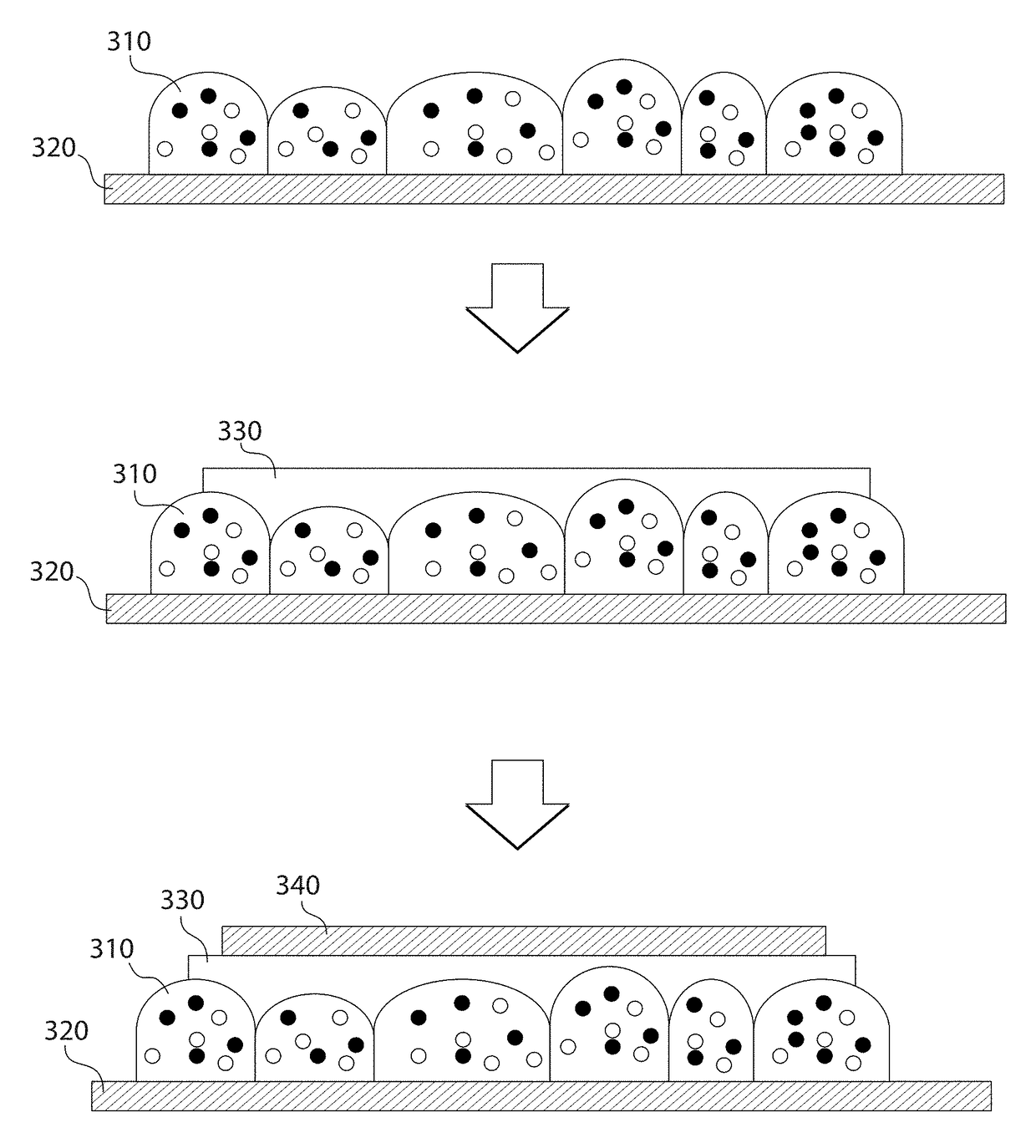
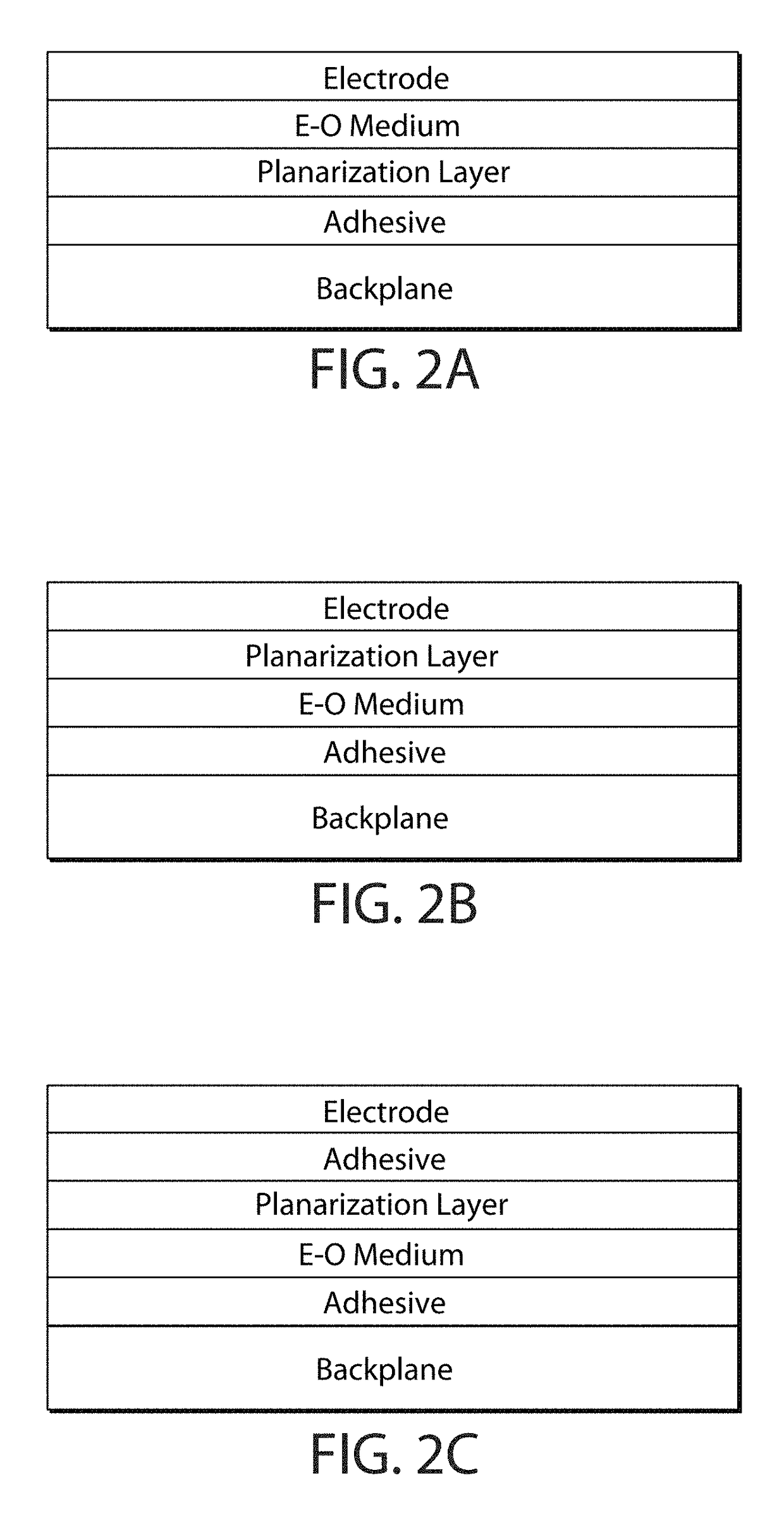
[0018]In another aspect, the polymer compositions of the invention can be incorporated into an electro-optic display. Such displays include an electro-optic medium, a conductive layer, and a polymer composition of the invention (i.e., a urethane acrylate, an adhesion promoter, and a conductive monomer). The electro-optic medium may include liquid crystals, electrochromic materials, or electrophoretic materials. In particular, electro-optic displays using encapsulated electrophoretic media (EEM) are improved with the use of the polymer compositions of the invention as a planarizing adhesive. Typically, during fabrication of a display using EEMs, the EEM layer is spread over a sheet of release or conductive material and dried or cured. Once spread, the layer of EEMs presents an irregular surface morphology that is not well-suited for bonding with another layer of release or electrode. The polymer composition of the invention can be used to smooth out the roughness of the surface of the EEM layer and to prepare the EEM layer to be bound to another substrate or electrode. Furthermore, because the volume resistivity of the polymer composition can be adjusted, the resistivity between electrodes can be modified for optimal performance under target working conditions.
[0022]By modifying the amount and type of conductive monomer and / or nanoparticle additives, it is possible to achieve an adhesive with a specific index of refraction, thereby allowing the use of a variety of electro-optic media and substrates depending upon the needs of the application. In an embodiment, the electro-optic medium may comprise a polymer-dispersed electrophoretic medium or an encapsulated electrophoretic medium. In some embodiments, the polymer composition will additionally include an ionic liquid, e.g., at a low concentrations.

Problems solved by technology

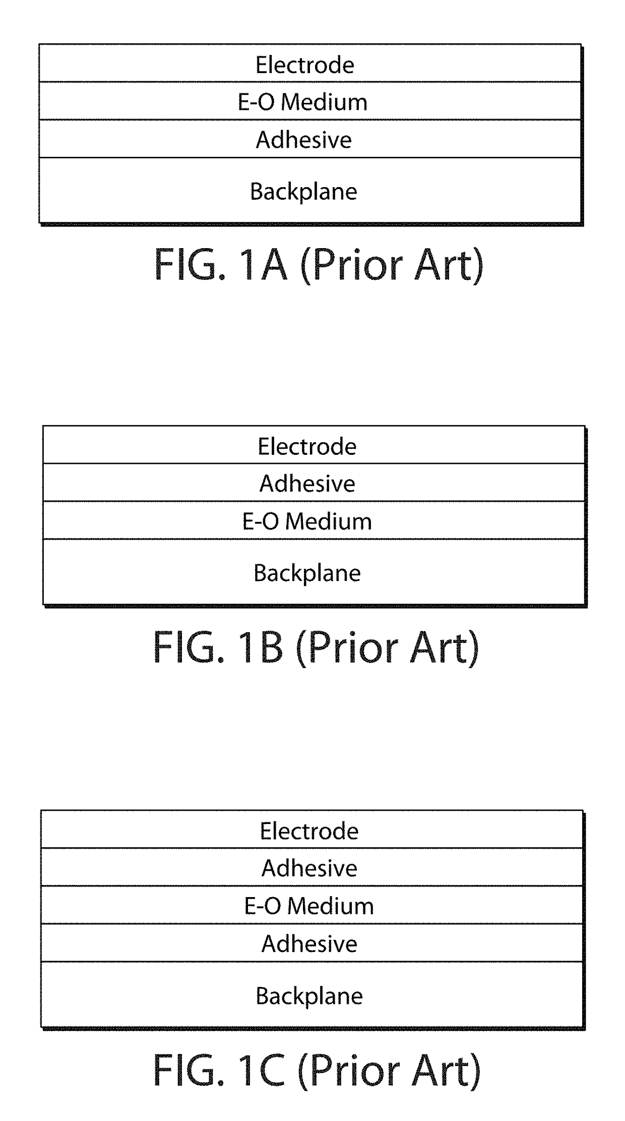
As discussed in U.S. Pat. Nos. 7,012,735 and 7,173,752, the selection of a lamination adhesive for use in an electro-optic display (or in a front plane laminate, inverted front plane laminate, double release film or other sub-assembly used to produce such an electro-optic display) presents certain problems.
On one hand, if the resistivity of the adhesive layer is too high, a substantial voltage drop will occur within the adhesive layer, requiring higher voltages between the electrodes to produce a working voltage drop at the electro-optic medium.
Increasing the voltage across the electrodes in this manner is undesirable, however, because it increases power consumption, and may require the use of more complex and expensive control circuitry to produce and switch the increased voltages.
On the other hand, if the resistivity of the adhesive layer is too low, there will be undesirable cross-talk between adjacent electrodes (i.e., active matrix electrodes) or the device may simply short out.
With experience, it was discovered that adhesives formulated with such dopants damage active matrix backplanes, especially those including transistors made from organic semiconductors.
Unfortunately, polyurethane compositions with salt and / or polymeric additives have been found to form voids when applied to electro-optic media having irregular surfaces.

Method used


Image

  • Polymer formulations for use with electro-optic media
  • Polymer formulations for use with electro-optic media
  • Polymer formulations for use with electro-optic media

Examples


example 1

Evaluation of Surface Planarity

[0115]A UV curable planarization layer including (meth)acrylated polyurethane oligomer resins was prepared for deposition on an encapsulated electrophoretic medium. The formulation was prepared by mixing 45 parts-per-hundred-resin(phr) (meth)acrylated resin (SR9088) and 15 phr polyester urethane diacrylate oligomer (CN964) and 40 phr acrylate oligomer (CN3108) in a bottle, heating the mixture to 60° C. for 2 hours, then rolling overnight, to produce a high-viscosity polymer mixture. After thorough mixing, 1 phr of 1-hydroxycyclohexyl-phenyl-ketone (CPK) photoinitiator and 1 phr of diphenyl(2,4,6-trimethylbenzoyl)phosphine oxide (TPO) photoinitiator were added, and the mixture was heated to 40° C. for 2 hours, and the formulation was rolled overnight, again, to homogenize the mixture.

[0116]The UV curing formulation described above was spread over an electro-optic medium on a release sheet using bar-coating, with the bar set for a 1 mil (25 μm) gap thick...

example 2

Evaluating Formulation Performance

[0119]In addition to providing improved planarity between the top electrode and the backplane, the formulations also improved the stability of a four-layer structure (electrode / electro-optic medium / planarization formulation / electrode) including the formulation. Structures including the formulation did not delaminate under strains that caused a similar four-layer structure (release / electro-optic medium / conventional adhesive / electrode) to delaminate.

[0120]Four-layer structures, containing planarization formulations in the place of conventional adhesive, also demonstrated improved performance, as measured by switching speed and dynamic range. This is likely due to conventional adhesives being roughly insulating when applied at thicknesses of 5-30 μm. Addition of a UV planarization layer to a layer of encapsulated bistable (black / white) electrophoretic medium coated directly on ITO showed a speed boost to both the white and the dark states with a 250 ms...

example 3

UV Polymer Formulations for VT Glass

[0123]Several UV-activated polymer formulations were prepared for use as adhesives and for planarizing a polymer-dispersed electrophoretic (PDEPID) layer or an encapsulated electrophoretic particle layer to be incorporated into VT glass. The formulations will be used to bond an ITO (PET / ITO front electrode) to the polyvinyl alcohol binder of a PDEPID skim coat, as depicted in FIG. 10B. While only variable transmission devices are exemplified below, a variable reflectivity device can be constructed using the same techniques, but using a reflective substrate in lieu of the transparent medium. Such a construction is shown in FIGS. 11A and 11B. Of course, switching variable transmission films that can be applied to existing substrates, e.g., windows, mirrors, signs, walls, metal, etc. In one embodiment of a variable reflectivity device, the reflective substrate is a mirror, e.g., silvered glass. In another embodiment, the reflective substrate is a mat...


PUM

PropertyMeasurementUnit
volume resistivityaaaaaaaaaa
particle sizeaaaaaaaaaa
atomic numberaaaaaaaaaa

Abstract

Polymer formulations including urethane acrylates, adhesion promoters, and conductive monomers. By selecting suitable conductive monomers, it is possible to achieve formulations having a volume resistivity from 106 to 1010 Ohm·cm after being conditioned for one week at 25° C. and 50% relative humidity. Such formulations are suitable for incorporation into electro-optic materials, such as electro-optic displays or variable transmission films, e.g., for architectural applications. In other embodiments, the formulations additionally include metal oxide nanoparticles to alter the refractive index and / or conductivity. The addition of certain metal nanoparticles additionally facilitates non-destructive measurement of layer thickness using X-ray fluorescence spectroscopy.

Description

REFERENCE TO RELATED APPLICATIONS[0001]This application claims priority to U.S. Provisional Application No. 62 / 195,943, filed Jul. 23, 2015, which is incorporated herein by reference in its entirety.[0002]This application is also related to U.S. Pat. No. 8,177,942 and copending application Ser. No. 14 / 692,854, filed Apr. 22, 2015 (Published as US 2015 / 0226986). The entire contents of the patent and copending applications, and of all other U.S. patents and published and copending applications mentioned below, are herein incorporated by reference.BACKGROUND OF INVENTION[0003]The invention relates to polymer formulations for use in the fabrication of electro-optic devices. Such devices can include a variety of electro-optic media, including electrophoretic media, electrochromic media, light-emitting diode media, or liquid crystal media. In particular, the invention is useful for improving the performance of layered assemblies including electro-optic media that are incorporated into ele...

Claims


Application Information

Patent Timeline
Patent Type & Authority Patents(United States)
IPC IPC(8): C09J175/06G02F1/167G02F1/15G01N23/223G02F1/1675
CPCC09J175/06G01N23/223G02F1/15G02F1/167G01N2223/633G02F1/1675C09J9/02C09J175/14C08K2201/011C08K2003/2244C08K2201/001C08K3/22G02F2202/28C09J175/16G02F1/133357C08F20/34C08F2/50C08F2/38C08J3/24C08J3/28C08K2201/005
Inventor WIDGER, PETER CARSTEN BAILEYMCCULLOUGH, LYNNE A.DEWITTE, RUSSELL J.PAOLINI, JR., RICHARD J.FAUVELL, THOMASNGUYEN, JONATHAN KIM
Owner E INK CORPORATION
Learn More