
Magnetically assisted electron impact ion source for mass spectrometry

Active Publication Date: 2017-08-01
BRUKER SCI LLC
View PDF11 Cites 6 Cited by
  • Summary
  • Abstract
  • Description
  • Claims
  • Application Information

AI Technical Summary

Benefits of technology

The invention is an electron emitter assembly for an ion source used in mass spectrometry. The assembly uses a magnet to guide electrons to the interaction region where gas molecules are ionized. Unlike previous arrangements, the second portion of unreacted electrons is carried along with the gas beam, increasing the ionization efficiency. The assembly also includes a wall to remove neutral molecules and form a well-defined gas beam. The electron emitter assembly may include a filament ring or coil and a repeller electrode-focusing lens assembly to increase electron density and likelihood of interaction. The use of multiple filaments can improve the robustness of the ion source.

Problems solved by technology

Nevertheless, the ionization area is still limited to a narrow confined space along the axis of the source while the sample molecules are introduced at right angle to the electron path and spread through the entire source volume.
So the ionization efficiency is still relatively small.
The disadvantage is poor ionization efficiency due to the poor electron beam confinement and single pass of the emitted electrons through the sample jet.
As a result, very large electron emission currents need to be used which leads to filament deformation in time and heat management complications.
One disadvantage would be the large current required for the solenoid to generate the necessary strong magnetic field, which requires significant cooling and limits the application of this source to large-dimension, high power instruments.
Another disadvantage would be the creation of a sort of “magnetic trap” on the gas jet path inside the solenoid body where a large number of electrons could accumulate over time ultimately leading to space charge issues.

Method used


Image

  • Magnetically assisted electron impact ion source for mass spectrometry
  • Magnetically assisted electron impact ion source for mass spectrometry
  • Magnetically assisted electron impact ion source for mass spectrometry

Examples


Embodiment Construction

[0038]While the invention has been shown and described with reference to a number of different embodiments thereof, it will be recognized by those skilled in the art that various changes in form and detail may be made herein without departing from the scope of the invention as defined by the appended claims.

[0039]FIG. 4 shows schematically a first embodiment of a magnetically assisted electron impact ion source for mass spectrometry according to principles of the invention. The source basically comprises two adjacent vacuum stages V1, V2, each being pumped down to the desired pressure by vacuum pumps indicated as P1 and P2. Suitable operating pressures could be ≦10−1 Pascal in V1 and ≦10−3 Pascal in V2, by way of example. The different pressure regimes are separated by a divider wall (1) that has a small opening (2) at its center. A gas nozzle N as ejector is located in the first vacuum stage V1, the tip of which points towards the wall opening (2). The nozzle N may be supplied with...


PUM


Abstract

The invention relates to a mass spectrometer having an electron impact ionization source which comprises an ejector for forming a beam of sample gas being driven in a first direction through an interaction region; a magnet assembly configured and arranged such that its magnetic field lines pass through the interaction region substantially parallel to the first direction; an electron emitter assembly for directing electrons toward the interaction region in a second direction being aligned substantially opposite to the first direction, wherein the electrons propagate along and are confined about the magnetic field lines until reaching the interaction region and forming sample gas ions therein; and a mass analyzer located downstream from the interaction region to which the sample gas ions are guided for mass analysis.

Description

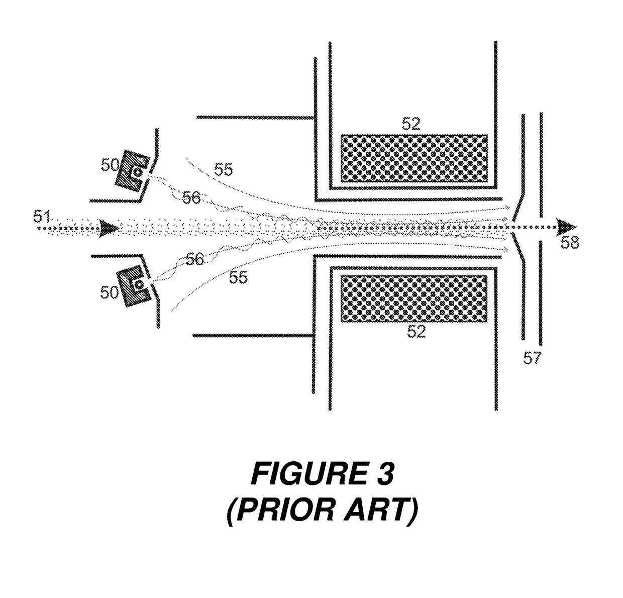
BACKGROUND OF THE INVENTION[0001]Field of the Invention[0002]The invention relates to electron impact ion sources for use in mass spectrometers, particularly in benchtop mass spectrometers, e.g. gas-chromatograph / mass-spectrometers (GCMS).[0003]Description of the Related Art[0004]Usually, gas-chromatograph / mass-spectrometer instruments use electron impact (EI) sources to create ions. In the most common prior art (see FIG. 1) the sample is vaporized in the GC and introduced into the source where the sample molecules are effusing from the end of a GC column (41) and bounce on the inside walls of the ionization chamber (40) creating a transient local pressure before they diffuse through the source openings and are pumped away. The EI source uses a filament assembly (42) with a straight filament that generates electrons, which are accelerated to typically seventy electron volts toward the ionization region where they collide with sample molecules and ionize. The electrons can be guided ...

Claims


Application Information

Patent Timeline
IPC IPC(8): H01J49/10H01J49/34H01J49/14G01N30/72H01J49/26
CPCH01J49/147H01J49/34H01J49/06H01J49/20
Inventor MUNTEAN, FELICIAN
Owner BRUKER SCI LLC
Learn More