
Multi-sensor based user interface

a multi-sensor, user-friendly technology, applied in biological models, instruments, reradiation, etc., can solve the problems of user interface design that is difficult to interact with and use, user distraction can be dangerous to the user and others, and the user interface design is not well suited or even insufficient. to achieve the effect of minimizing distraction

Active Publication Date: 2017-03-02
NVIDIA CORP
View PDF29 Cites 188 Cited by
  • Summary
  • Abstract
  • Description
  • Claims
  • Application Information

AI Technical Summary

Benefits of technology

[0006]Accordingly, what is needed is a user interface solution to allow interaction and / or control of a computing system in an intuitive and natural way while minimizing distraction.
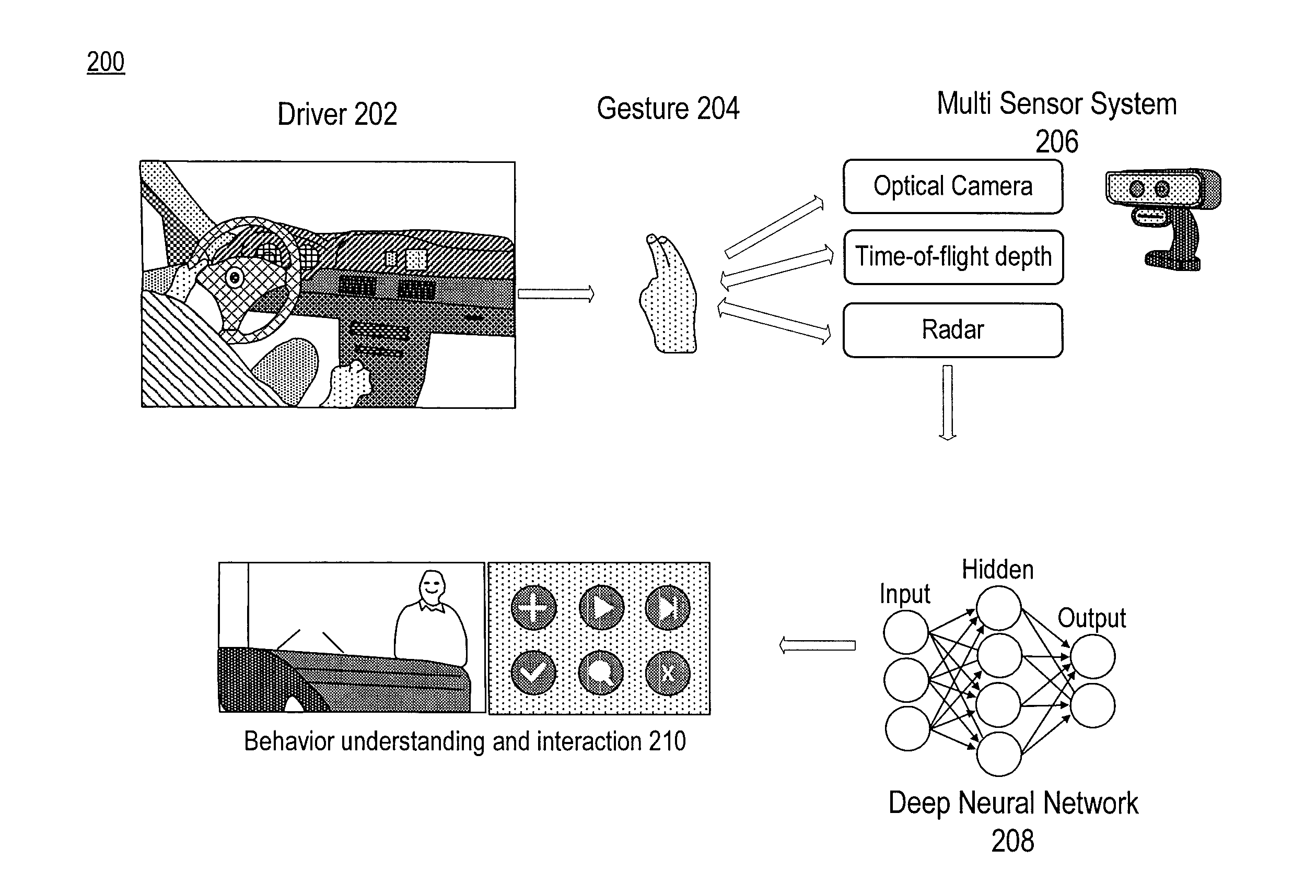
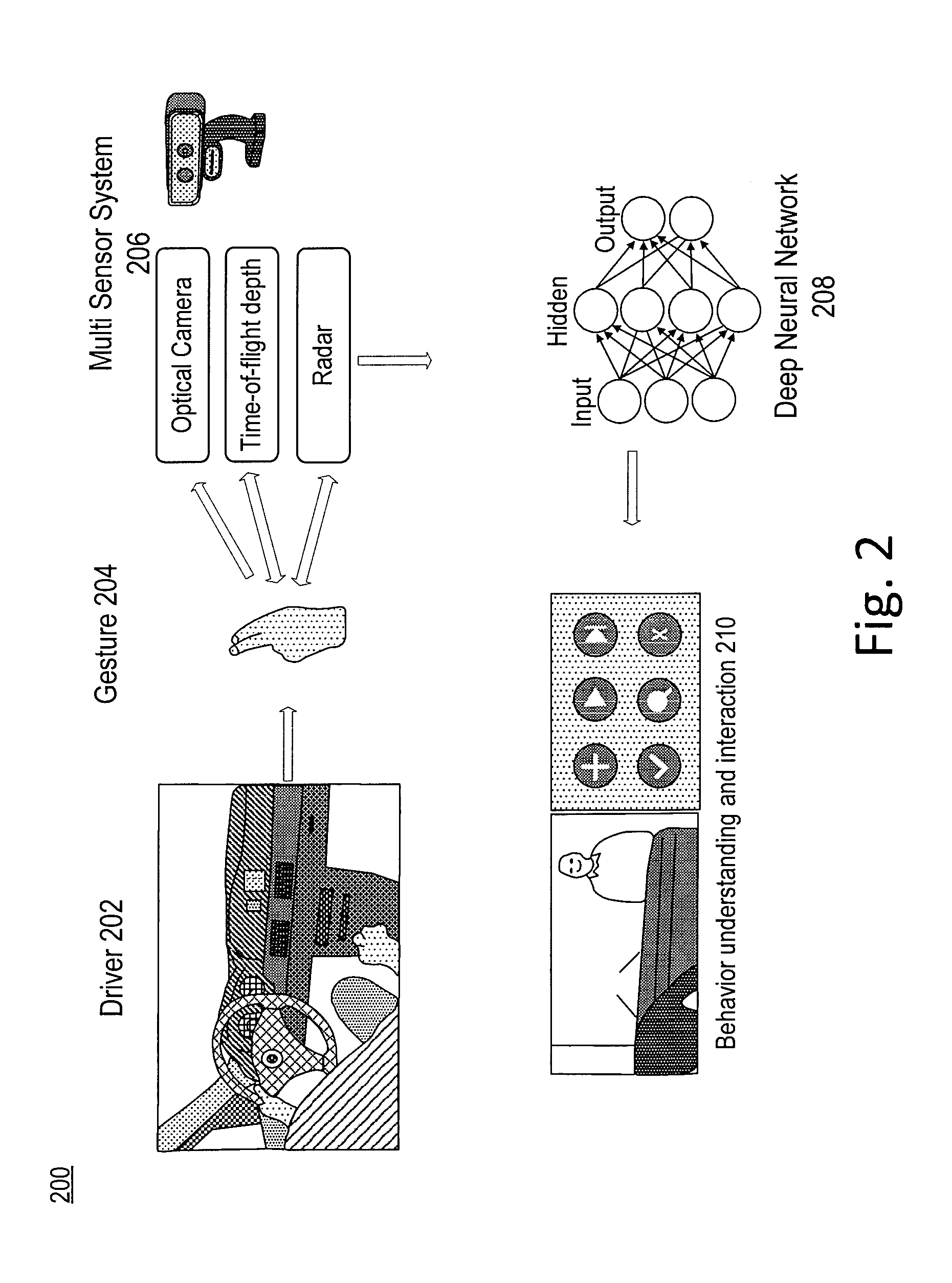
[0007]Embodiments allow for gesture recognition thereby allowing users to interact with computing devices in a natural manner with reduced distraction. Improved accuracy and robustness to a variety of lighting conditions is provided through use of a plurality of sensors. Power consumption can also be reduced through selective operation of the plurality of sensors. Embodiments include a novel multi-sensor system for accurate and power-efficient dynamic (e.g., car-driver) hand-gesture recognition, e.g., using a short-range radar, a color camera, and a depth camera. The combination of the multiple sensors together makes the system robust to variable lighting conditions. In some embodiments, the radar and depth sensors are jointly calibrated. Embodiments can employ convolutional deep neural networks to fuse data from the multiple sensors and to classify the gestures. In an example embodiment, ten different gestures acquired under various illuminating conditions including indoors and outdoors and in a car during the day and at night are recognized. The multi-sensor system consumes significantly less power through selective activation of the sensors than purely vision-based systems. Embodiments can be used in a variety of vehicles including, but not limited to, wagons, bicycles, motor vehicles (e.g., motorcycles, cars, trucks, and buses), railed vehicles (e.g., trains, trams), watercraft (e.g., ships, boats), aircraft and spacecraft.

Problems solved by technology

The proliferation of computing systems into new areas of use, such as within vehicles, has resulted in previous user interface designs being not well suited or even insufficient.
As a result, user interface designs can be difficult for users to interact with and use, particularly in the automobile environment.
This distraction can be dangerous to the user and others when in a moving vehicle.

Method used


Image

  • Multi-sensor based user interface
  • Multi-sensor based user interface
  • Multi-sensor based user interface

Examples


Embodiment Construction

[0033]Reference will now be made in detail to the preferred embodiments of the present invention, examples of which are illustrated in the accompanying drawings. While the invention will be described in conjunction with the preferred embodiments, it will be understood that they are not intended to limit the invention to these embodiments. On the contrary, the invention is intended to cover alternatives, modifications and equivalents, which may be included within the spirit and scope of the invention as defined by the appended claims. Furthermore, in the following detailed description of embodiments of the present invention, numerous specific details are set forth in order to provide a thorough understanding of the present invention. However, it will be recognized by one of ordinary skill in the art that the present invention may be practiced without these specific details. In other instances, well-known methods, procedures, components, and circuits have not been described in detail ...


PUM


Abstract

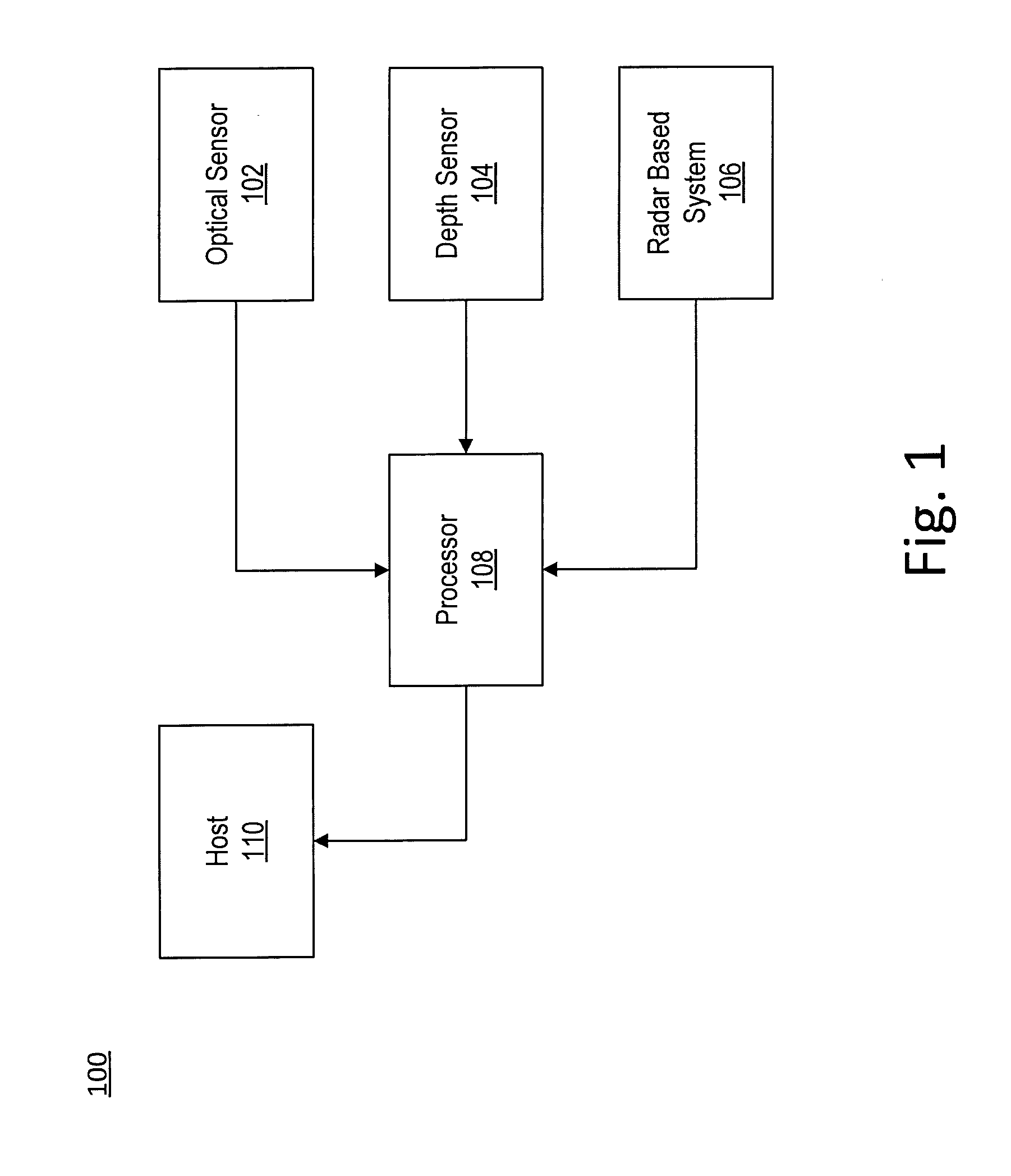
An apparatus and method for gesture detection and recognition. The apparatus includes a processing element, a radar sensor, a depth sensor, and an optical sensor. The radar sensor, the depth sensor, and the optical sensor are coupled to the processing element, and the radar sensor, the depth sensor, and the optical sensor are configured for short range gesture detection and recognition. The processing element is further configured to detect and recognize a hand gesture based on data acquired with the radar sensor, the depth sensor, and the optical sensor.

Description

RELATED U.S. APPLICATIONS[0001]This application claims the benefit of and priority to the copending provisional patent application, Ser. No. 62 / 127,759, Attorney Docket Number NVID-P-SC-14-0340-US0, entitled “MULTI-SENSOR SYSTEM FOR DRIVER'S HAND GESTURE RECOGNITION,” with filing date Mar. 3, 2015, and is hereby incorporated by reference in its entirety.[0002]This application claims the benefit of and priority to the copending provisional patent application, Ser. No. 62 / 127,754, Attorney Docket Number NVID-P-SC-14-0339-US0, entitled “IN-VEHICLE SHORT-RANGE RADAR SYSTEM FOR INTELLIGENT UIs,” with filing date Mar. 3, 2015, and is hereby incorporated by reference in its entirety.[0003]This application is related to non-provisional patent application, Ser. No. ______, Attorney Docket Number NVID-P-SC-14-0339-US1, entitled “RADAR BASED USER INTERFACE,” with filing date ______, 2016, and is hereby incorporated by reference in its entirety.FIELD[0004]Embodiments of the present invention ar...

Claims


Application Information

Patent Timeline
Patent Type & Authority Applications(United States)
IPC IPC(8): G06F3/01G06K9/62B60R11/04G06N3/04G06N3/08G06K9/00G06K9/78
CPCG06F3/017G06K9/00355G06K9/6288G06K9/78B60R11/04G06K9/6267G06N3/04G06N3/08G06K9/6256G01S7/415G01S13/584G06F3/011G06N3/082G06N3/084G01S13/42G01S7/352G01S13/4454G01S7/0233G01S7/0234G06N3/045G06V40/28G06F18/24G06F18/25G06F18/214
Inventor MOLCHANOV, PAVLOGUPTA, SHALINIKIM, KIHWANPULLI, KARI
Owner NVIDIA CORP
Learn More