
Insulation systems having improved partial discharge resistance, and method for producing same

a technology of partial discharge and insulation system, which is applied in the direction of inorganic insulators, plastic/resin/waxes insulators, inhomogeneous insulation materials, etc., can solve the problems of rapid degradation of polymeric matrix on exposure to partial discharge, electric breakdown of insulators, and specific increase in individual coil costs, etc., to achieve the effect of improving partial discharge resistan

Inactive Publication Date: 2017-03-07
SIEMENS AG
View PDF16 Cites 5 Cited by
  • Summary
  • Abstract
  • Description
  • Claims
  • Application Information

AI Technical Summary

Benefits of technology

The present invention relates to an insulating system with improved resistance to partial discharge. The invention involves using an insulating tape that is wound around an electrical conductor and includes a mica tape joined to a carrier material. The insulating tape is impregnated with a synthetic resin, which is interspersed with a nanoparticulate filler. The use of adhesion promoters, particularly silanes, has been found to inhibit erosion. The patent text also mentions the synergistic use of a passivation coat and organosilanes, which enhances the erosion resistance of the insulating system. The use of organosilanes as part of the resin formulation allows for higher concentrations and the use of a greater number of silanes.

Problems solved by technology

The fundamental problem with insulators loaded electrically in this way lies in the so-called partial discharge-induced erosion with formation of what are called “treeing” channels, which lead ultimately to the electrical breakdown of the insulator.
In contrast to this, the manufacture of Resin Rich coils is more complex, since each coil leg or winding bar has to be manufactured individually in specific baking presses, leading to a specific increase in the costs of the individual coil.
A disadvantage of the known systems, especially of those based on epoxy resins, is the rapid degradation of the polymeric matrix on exposure to partial discharge, here referred to as erosion.

Method used


Image

  • Insulation systems having improved partial discharge resistance, and method for producing same
  • Insulation systems having improved partial discharge resistance, and method for producing same
  • Insulation systems having improved partial discharge resistance, and method for producing same

Examples


Embodiment Construction

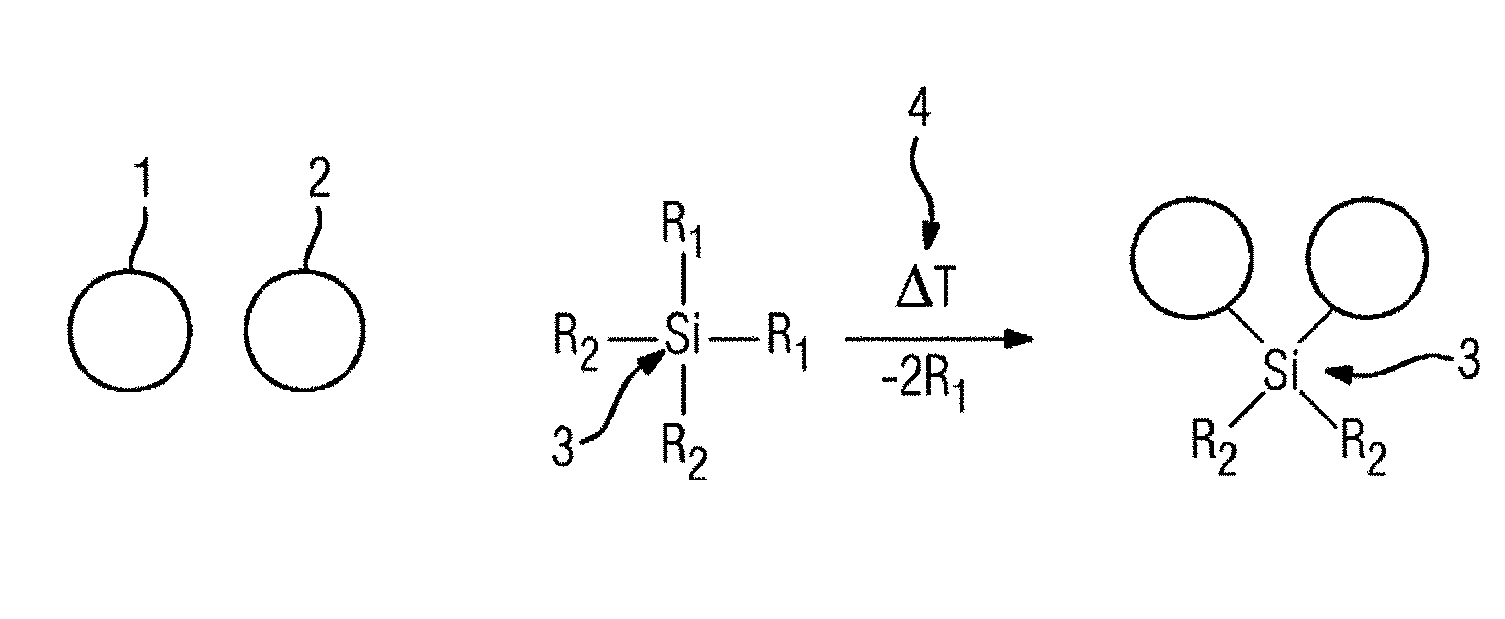
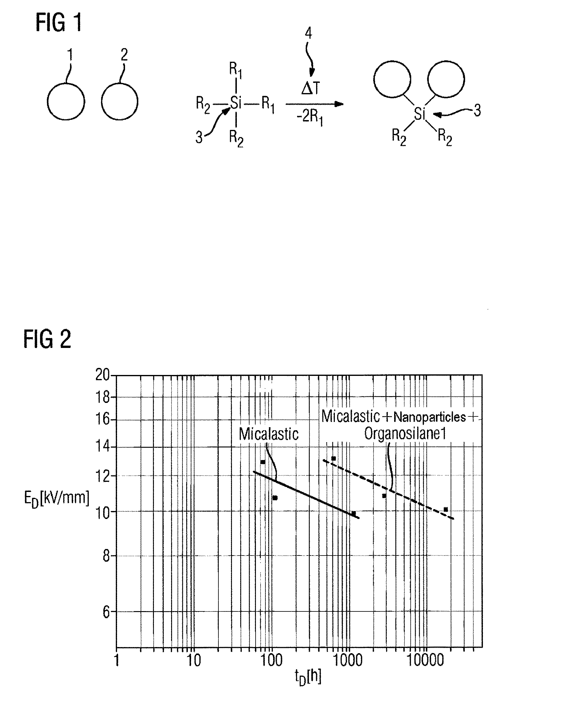
[0046]FIG. 1 shows schematically a general mechanism for in situ particle crosslinking, using a difunctional organosilane as an example. Fundamentally, silanes may possess one to four reactive functional groups, in order to exert a positive effect on the erosion resistance. These functional groups have the property of being able to react with the particle surface, resulting in the large spectrum of organosilanes.

[0047]The mechanism of particle crosslinking proposed in FIG. 1 with a difunctional silane; R1=hydroxyl, alkoxy, halogen, glycidyloxy; R2=alkyl, glycidyloxy, vinyl, propylsuccinic anhydride, methacryloyloxypropyl shows the substitution of the radicals R1 on the silane by nanoparticles. R2 also be amidic, sulfidic, oxidic, or H. “Amidic, oxidic, and sulfidic” here means that further organic R′2 may be present, bonded to the silicon via nitrogen, oxygen, or sulfur.

[0048]The particles 1 and 2 are both bonded to the silicon core 3 by substitution of the radicals R1 on said core ...


PUM

PropertyMeasurementUnit
particle sizeaaaaaaaaaa
temperaturesaaaaaaaaaa
particle sizeaaaaaaaaaa

Abstract

Disclosed are insulating electric conductors against partial discharge and a method for producing an insulation system having improved partial discharge resistance and such an insulation system. There is an erosion-inhibiting effect of adhesion promoters, such as organic silicon compounds, added to resin when admixing nano particulate fillers. Good results may be attributable to a type of particle wetting of the nano particles as a result of particle wetting with organosilanes. The admixture of adhesion promoters with the resin before the addition of the nano particulate filler provides considerable advantages.

Description

CROSS-REFERENCE TO RELATED APPLICATIONS[0001]The present application is a 35 U.S.C. §§371 national phase conversion of PCT / EP2012 / 067141, filed Sep. 3, 2012, which claims priority of German Patent Application No. 102011083228.9, filed Sep. 22, 2011, the contents of which are incorporated by reference herein. The PCT International Application was published in the German language.Technical Field[0002]Insulation systems having improved partial discharge resistance, and method for producing same.[0003]The present invention pertains generally to the field of the insulation of electrical conductors against partial discharge, and specifically to a method for producing an insulating system having improved partial discharge resistance and to an insulating system having improved partial discharge resistance.BACKGROUND OF THE INVENTION[0004]In rotating electrical machines, such as motors or generators, the reliability of the insulating system is critically responsible for their operational int...

Claims


Application Information

Patent Timeline
Patent Type & Authority Patents(United States)
IPC IPC(8): H01B3/40H01B3/04B82Y30/00H01B19/04H01B3/00H01B19/02
CPCH01B3/04B82Y30/00H01B3/002H01B3/40H01B19/02H01B19/04
Inventor GROPPEL, PETERHEINL, DIETERMEICHSNER, CHRISTIANRITBERG, IGOR
Owner SIEMENS AG
Learn More