Mono-metallic thermocouples
a mono-metallic, thermocouple technology, applied in the direction of material nanotechnology, pyrometry using electric radation detectors, optical radiation measurement, etc., can solve the problems of inability to control the fabrication process, the complexity of bi-metallic thermocouple fabrication, and the inability to manufacture the requisite control methods and fabrication methods at sub-micron scale, so as to reduce the complexity of mono-metallic nanowire tcs, the effect of smooth variation in width and
- Summary
- Abstract
- Description
- Claims
- Application Information
AI Technical Summary
Benefits of technology
Problems solved by technology
Method used
Image

Examples
example 1
Thermocouple Design and Functionality
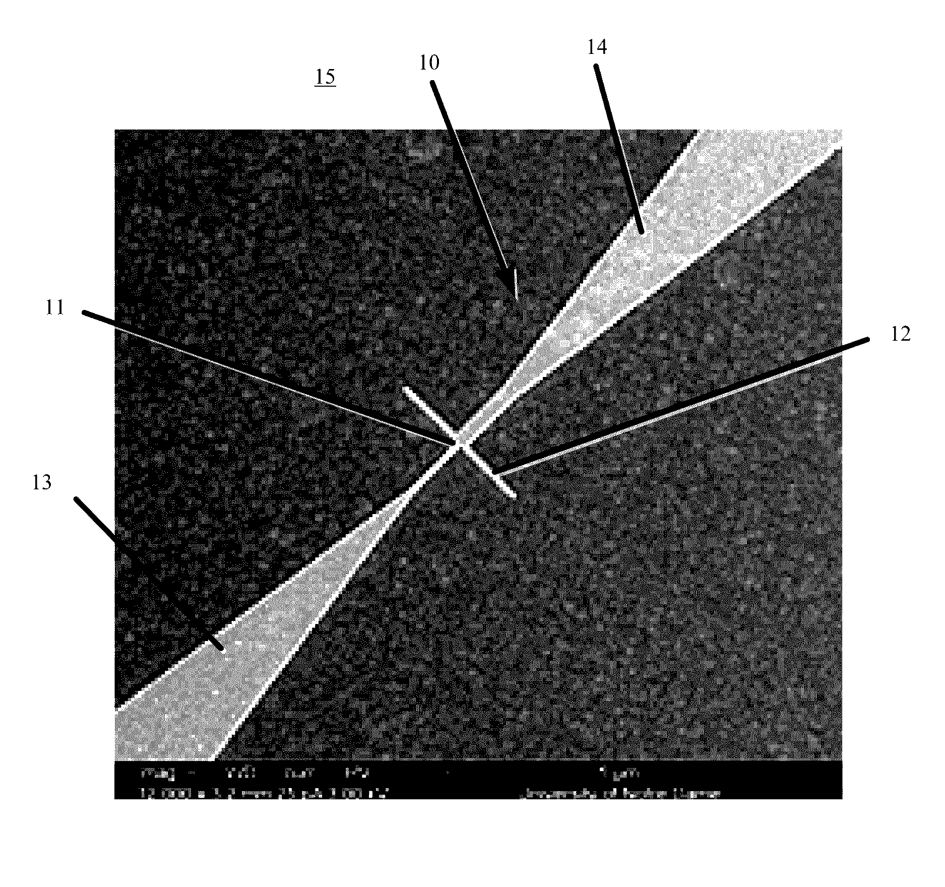
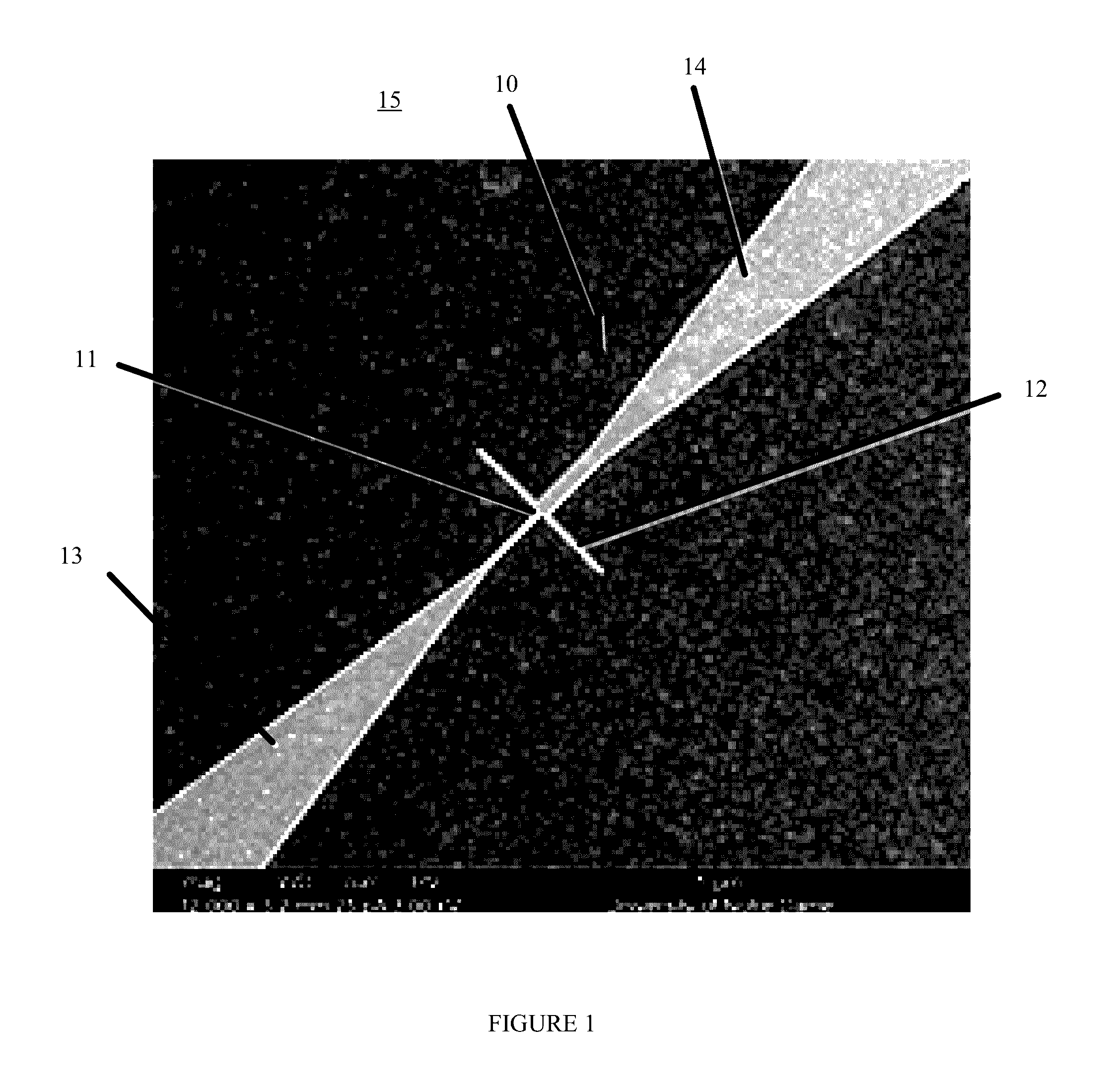
[0029]This example demonstrates the existence of a thermoelectric effect based on a cross-sectional discontinuity in single-metal wires.
[0030]Referring to FIG. 6, fabricated shape-engineered thermocouples 60 were connected to bonding pads and located about 25 μm away from a bank of resistance heaters 62. Simulations and temperature measurements using resistance temperature detectors (RTDs) located in close proximity to these junctions confirmed that the temperature remained unchanged for any combination of heater currents used in the experiments within 10 mK accuracy.
[0031]Measurements of the shape-engineered TC 61 used the 2ω method which is herein described. For an AC heater current I(ω)=I0 cos(ωt) with an angular frequency (ω) and amplitude (I0), the power dissipated due to Joule heating is proportional to the square of the current:
P=I02R / 2*(1+cos(2ωt)) Eqn (2)
where R is heater resistance. Because R is a weak function of I, varying by less th...
example 2
Relative Seebeck Coefficient Calculation
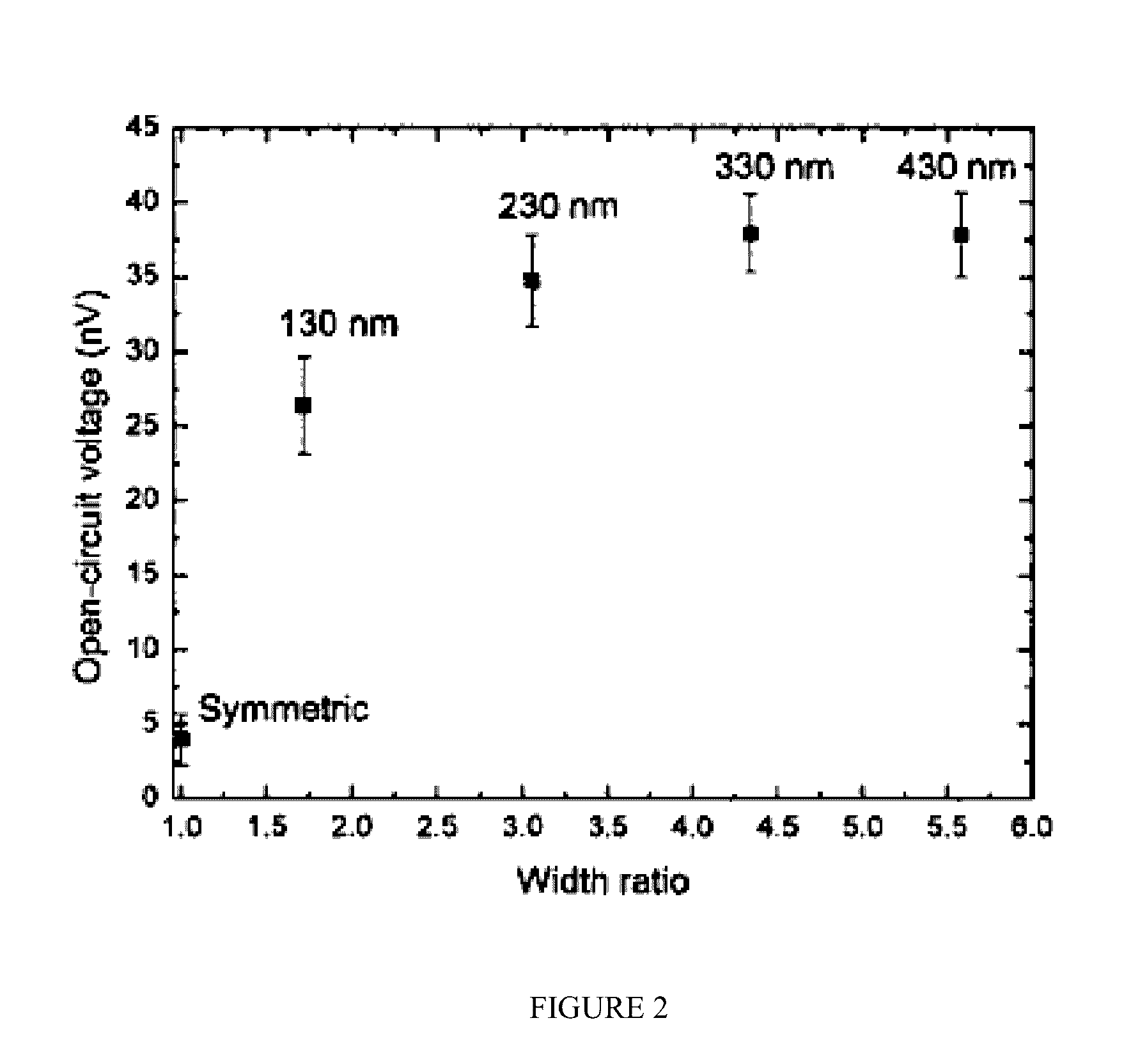
[0042]Direct determination of the relative Seebeck coefficient of the shape-engineered TCs requires measurement of the temperature difference simultaneously with that of the open-circuit voltage. Temperature measurement was accomplished by Kelvin sensing using a four-probe resistance calibrated temperature detector (RTD) placed in proximity to the hot junction of shape-engineered TCs with various different cross sectional widths. In particular the shape-engineered thermocouples that were studied all had one segment that was 50 nm wide while the wider segment width varied from 100 to 350 nm. Relative Seebeck coefficients of these shape-engineered TCs were directly obtained using simultaneous measurements of the open-circuit voltages and temperature differences for various heater currents. The temperature hot junction of the shape-engineered thermocouple was sensed by the nearby temperature detector. The open-circuit voltage of the TC as a funct...
example 3
ACSET Fabrication
[0048]This example demonstrates the fabrication of shape-engineered thermocouples. Fabrication of the characterization platform and of the antenna-coupled shape-engineered thermocouples involved electron beam lithography and a single metal deposition, greatly reducing the fabrication complexity compared to the bi-metallic antenna-coupled thermocouples. Nanoimprint lithography tools can also be used to allow a single metal device to be fabricated with nanoscale features.
[0049]In one embodiment, a dipole antenna is attached to the shape-engineered thermocouple. While the discontinuous junction is illustrated as being located at the center of the antenna, it can be otherwise located as may be required and / or desired in other embodiments. Joule heating of the junction occurs due to the radiation-induced antenna currents. The geometry of the antenna determines the resonant frequency, the directivity, and the polarization of the detector. Different antenna configurations ...
PUM
 Abstract
Description
Claims
Application Information
 - R&D
- Intellectual Property
- Life Sciences
- Materials
- Tech Scout
- Unparalleled Data Quality
- Higher Quality Content
- 60% Fewer Hallucinations
Browse by: Latest US Patents, China's latest patents, Technical Efficacy Thesaurus, Application Domain, Technology Topic, Popular Technical Reports.
© 2025 PatSnap. All rights reserved.Legal|Privacy policy|Modern Slavery Act Transparency Statement|Sitemap|About US| Contact US: help@patsnap.com