Method and apparatus for managing ooze from a print nozzle

a technology of nozzle and print nozzle, which is applied in the field of three-dimensional object printing methods and apparatuses, can solve the problems of messy print, net loss of extrusion, and inability to meet the needs of production, and achieves the effects of more well-defined end products, more accurate printing, and even track width

Inactive Publication Date: 2021-09-23
ULTIMAKER BV
View PDF3 Cites 0 Cited by
  • Summary
  • Abstract
  • Description
  • Claims
  • Application Information

AI Technical Summary

Benefits of technology

The present invention provides a method and system for printing separated islands of material without retracting the nozzle or interrupting the flow of print material to the nozzle. This allows for a constant pressure within the nozzle, resulting in an even track width and improved printing accuracy. The method also allows for the creation of a thin connection portion between the first and second islands, which can be easily removed from the main islands. The device used for printing the three-dimensional object includes a print nozzle, a staging surface, and a control system. The control system controls the movement of the print nozzle relative to the staging surface and ensures that there is no interruption of the flow of print material to the nozzle during the printing process. The method and device provide for a more efficient and effective printing process.

Problems solved by technology

Such a “stop-and-go” technique is not an attractive solution for flexible filament materials as such filaments tend to be compressed between the filament feeder unit and the nozzle, for example.
By the time you have retracted the compressed material, the material will have oozed and leaked from the nozzle, leading to a messy print, often with apparent under extrusion.
Retracting compressed material also results in a net loss of extrusion as you unretract less uncompressed material with the same number of extrusion steps.
However, both of the above scenarios result in apparent under extrusion due to material loss by filament oozing or from the time required to build up pressure because of the relatively slow pressurization dynamics in the printer head and the nozzle to achieve the required flow rate when the printing process resumes.
Syringe based additive manufacturing systems suffer from similar drawbacks.
In such systems, the removal of back pressure (from the build surface) leads to a drop-in pressure within the syringe volume, thus leading to uneven pressure throughout the printing process, and a messy finish on the printed item.

Method used


Image

  • Method and apparatus for managing ooze from a print nozzle
  • Method and apparatus for managing ooze from a print nozzle
  • Method and apparatus for managing ooze from a print nozzle

Examples


Embodiment Construction

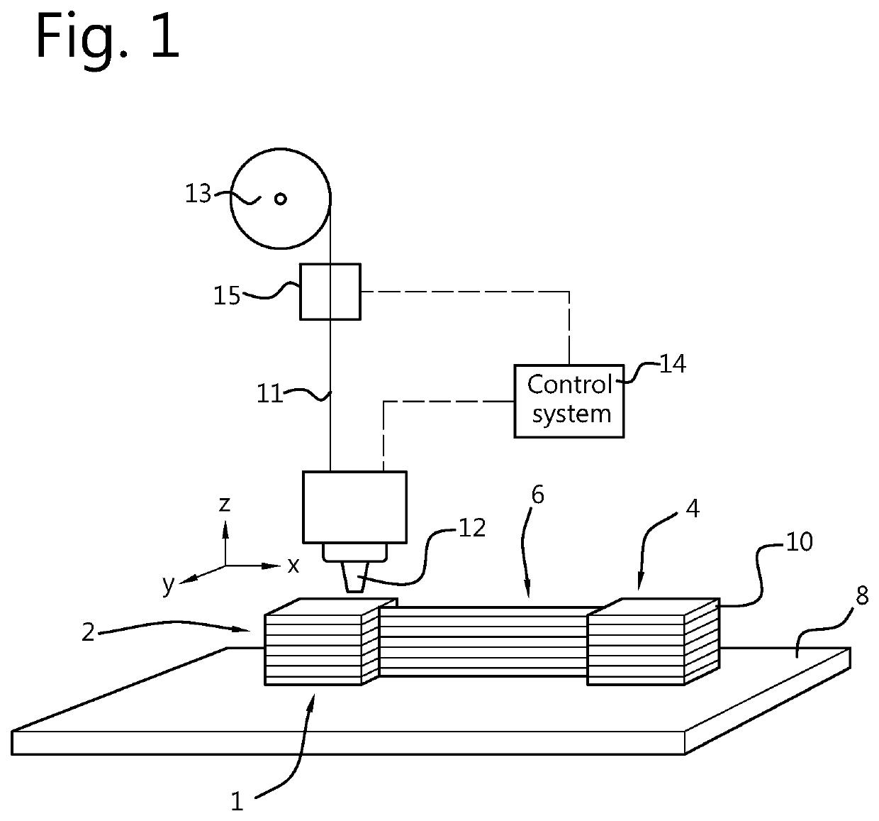
[0029]FIG. 1 shows a simplified schematic of a printer assembly for printing a three-dimensional object, according to an embodiment of the present invention. As shown in FIG. 1, the three-dimensional object 1 comprises at least one layer formed of a first region 2 of printed material and a second region 4 of printed material. The first region 2 is separated from the second region 4 by a space in which there is formed at least one layer formed of an intermediate region 6.

[0030]The printer assembly comprises a print nozzle 12 configured to deliver a flowable print material and a staging surface 8 onto which successive layers 10 of print material can be printed to form the three-dimensional object. A control system 14 is provided to control movement of the print nozzle 12 relative to the staging surface 8 and is configured to move the nozzle during a printing process. In this example, the printer assembly is an FDM print assembly wherein a filament 11 is fed by means of a feeder unit 1...


PUM

PropertyMeasurementUnit
Angleaaaaaaaaaa
Angleaaaaaaaaaa
Speedaaaaaaaaaa

Abstract

A method of printing an object comprises a first step in which a first region (2) is printed by delivering flowable material from a print nozzle travelling at a first print speed (V1). During a second step, an intermediate region (6) is printed by delivering material from the nozzle travelling (8) for: a first travel distance (D1) at a first travel speed (S1), a second travel distance (D2) at a second travel speed (S2), and a third travel distance (D3) at a third travel speed (S3). In a third step, the nozzle prints a second region 4 by delivering material from the nozzle travelling at a second print speed (V2). The first and third travel speeds (S1, S3) are both greater than the first and second print speeds (V1, V2) and the second travel speed (S2).

Description

FIELD OF THE INVENTION[0001]The present invention relates to a method and apparatus for printing a three-dimensional object. It also relates to a method of controlling a device for printing a three-dimensional object, and to a computer program product.BACKGROUND OF THE INVENTION[0002]Fused deposition modelling or FDM is a material extrusion type additive manufacturing technique and is currently the most widely used 3D printing technology. FDM systems generally comprise an extrusion head, suitably mounted to allow movement of the extrusion head in the X, Y and Z directions. During operation, thermoplastic filament is heated to a desired temperature and fed to a nozzle where it melts and is deposited in successive layers in predetermined locations.[0003]In order to print two or more islands with FDM printing, it is generally desirable to interrupt the flow of thermoplastic filament from the nozzle in some way to prevent the islands being joined by a strip of printed material. One meth...

Claims


Application Information

Patent Timeline
IPC IPC(8): B29C64/118B33Y10/00B33Y30/00B33Y50/02B29C64/393
CPCB29C64/118B33Y10/00B29K2075/00B33Y50/02B29C64/393B33Y30/00
Inventor CANDLER, PAUL ANTHONY
Owner ULTIMAKER BV
Why Eureka
Try Eureka