Bimorph optical element

a technology of optical elements and optical elements, applied in the field of bimorph optical elements, can solve the problems of limited stability, difficult implementation of laminated structures, and limited quality of mirror polishing

Active Publication Date: 2013-06-25
SOC EURO SYST OPTIQUES
View PDF6 Cites 0 Cited by
  • Summary
  • Abstract
  • Description
  • Claims
  • Application Information

AI Technical Summary

Benefits of technology

[0021]Because of the improved coupling between the ceramic and the mirror, that action gives rise to better accuracy and better stability of the mirror when it is curved.
[0022]Since the ceramics are no longer under or on the optical surface, junctions between the ceramic elements are less visible and the effect of such junctions is smoothed over the width of the mirror.
[0023]Unlike the description of application EP 1 835 302, the structure of the present invention is symmetrical about the neutral axis of the optical element, thereby avoiding any bimetal-type thermal effect (even if industrial bars may be made up of a plurality of ceramic elements that are adhesively bonded together), thereby giving very good thermal stability.

Problems solved by technology

Implementing a laminated structure is relatively complicated and difficult.
The laminated structure concept used for bimorph mirrors also limits the dimensions of such mirrors to the dimensions of ceramic elements and to multiples thereof, and the quality with which the mirror is polished is limited by the presence of the laminated structure.
When the ceramic bars are bimorphs, i.e. when the bars comprise two pieces of ceramic stuck back to back, stability is limited by a bimetal type effect when the temperature of the assembly changes.
These advantages are of particular interest when a traditional mirror is being transformed into a bimorph mirror, since the solution of applying ceramics (monomorphs or bimorphs) to the rear face is a poor adaptation, giving rise to a smaller dynamic range and suffering from a bimetal-type thermal effect.

Method used


Image

  • Bimorph optical element
  • Bimorph optical element
  • Bimorph optical element

Examples


Embodiment Construction

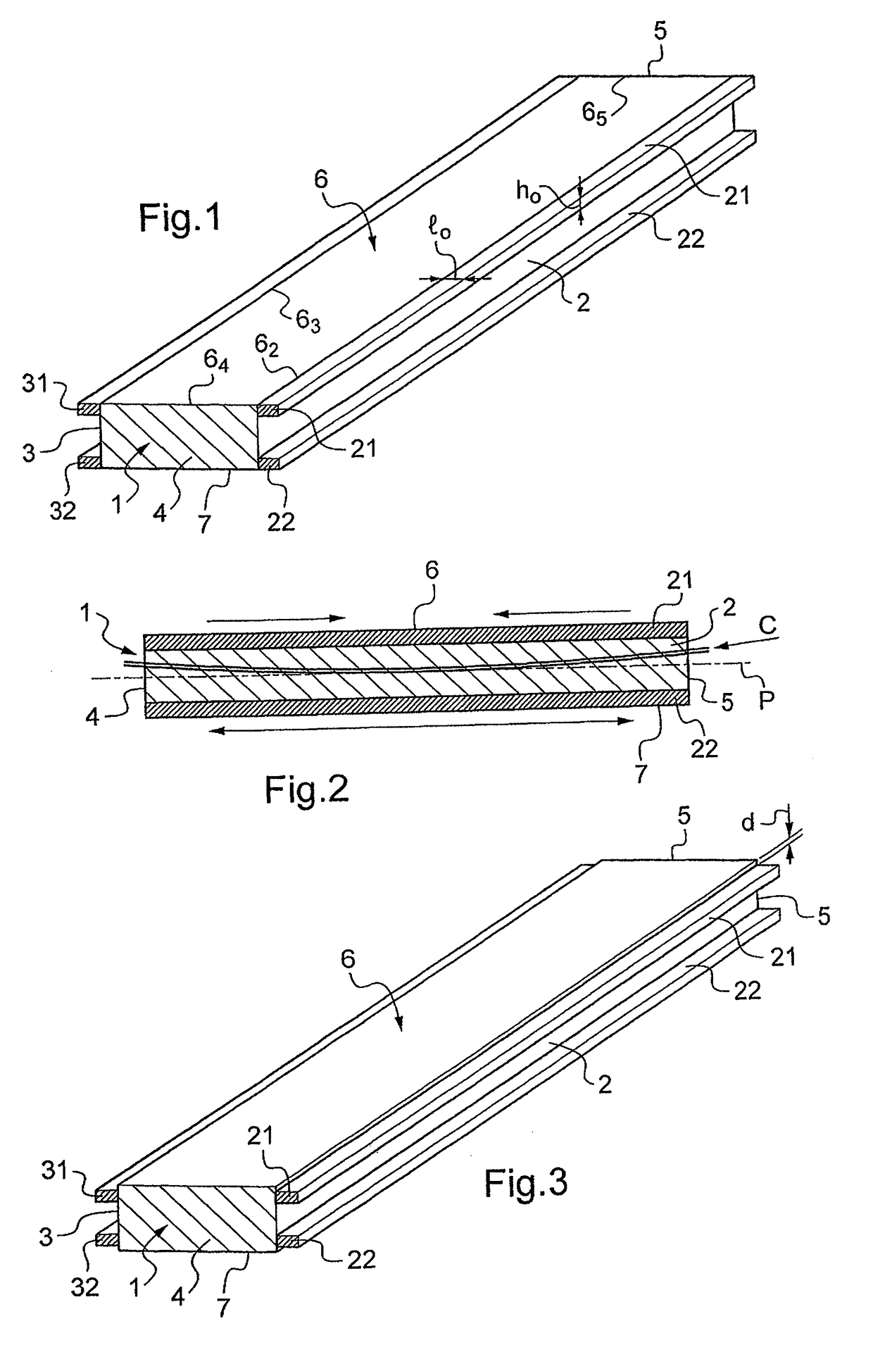
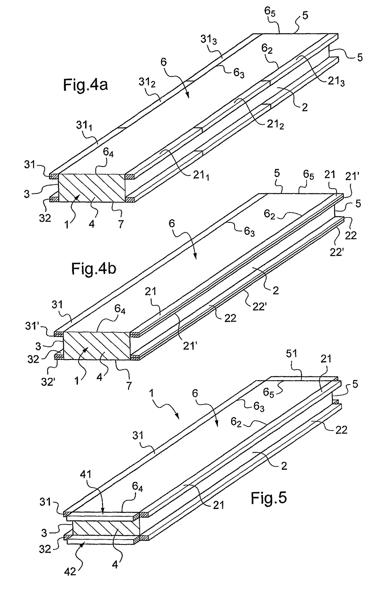
[0046]FIG. 1 shows a deformable optical element 1 of rectangular shape that presents two main lateral faces 2 and 3 along the long side of the rectangle and two end lateral faces 4 and 5. The top face 6 presents an optical function, for example it is polished so as to form a mirror that is plane or curved (concave or convex) in the longitudinal direction and / or in the transverse direction, or else it carries one or more grating patterns with lines that are perpendicular to the long sides of the rectangle or parallel thereto, for example, so as to form a grating that is plane or curved (concave or convex) in the longitudinal direction and / or in the transverse direction and that operates in reflection or in diffraction.

[0047]The lateral face 2 carries a first pair of piezoelectric bars 21, 22 that are substantially parallel to the midplane P (drawn in chain-dotted lines in FIG. 2) of the optical element 1 and defining the neutral axis (when the planes 6 and 7 are plane or curved only ...


PUM


Abstract

The invention relates to a bimorph optical device comprising a deformable optical element and active elements made of piezoelectric ceramic provided with electrodes, said elements being controlled in pairs and in opposition so as to produce a compression movement for a first element of a pair and an extension movement for the second element of a pair, the device being characterized in that the optical element (1) presents an optically active first main surface (6) and a second main surface (7) opposite to the first main surface, together with at least first and second opposite lateral faces (2, 3), and in that the ceramic active elements comprise at least two pairs of bars (21, 22; 31, 32) of piezoelectric ceramic placed facing each other on said first and second lateral faces (2, 3), each pair comprising two bars (21, 22; 31, 32) placed on one of the first and second lateral faces (2, 3) on either side of a middle surface of the optical element (1) that constitutes the neutral axis thereof.

Description

FIELD OF THE INVENTION[0001]The present invention provides a bimorph optical element controlled by active elements made of piezoelectric ceramic that are actuated in opposition.BACKGROUND[0002]European patent application EP 1 723 461 relates to a bimorph mirror presenting two ceramic layers having electrodes and spaced apart by a central core.[0003]Such a mirror is assembled in the form of a laminated structure having two so-called “skin” layers, at least one of which is used as a mirror, with the two ceramic layers and the central core being sandwiched between the two skin layers.[0004]Implementing a laminated structure is relatively complicated and difficult.[0005]The laminated structure concept used for bimorph mirrors also limits the dimensions of such mirrors to the dimensions of ceramic elements and to multiples thereof, and the quality with which the mirror is polished is limited by the presence of the laminated structure.[0006]Solutions known in the prior art have always bee...

Claims


Application Information

Patent Timeline
Patent Type & Authority Patents(United States)
IPC IPC(8): G02B5/08
CPCG02B26/0825
Inventor CARRE, JEAN-FRANCOIS
Owner SOC EURO SYST OPTIQUES
Why Eureka
Try Eureka