
Lithium secondary battery with excellent performance

a secondary battery and excellent technology, applied in the direction of batteries, wound/folded electrode electrodes, sustainable manufacturing/processing, etc., can solve the problems of human body, difficult to synthesize, disadvantageous economic efficiency of licoo/sub>2

Active Publication Date: 2017-02-07
LG ENERGY SOLUTION LTD
View PDF26 Cites 0 Cited by
  • Summary
  • Abstract
  • Description
  • Claims
  • Application Information

AI Technical Summary

Benefits of technology

The present invention aims to prevent the oxidation of an electrolyte in a lithium secondary battery, even when using a high-voltage cathode. The invention achieves this by controlling the charge cut-off voltage and the potential of the cathode and anode. By doing so, the inventors have developed a method to prevent the formation of gases and byproducts, which reduces battery performance and increases resistance. Additionally, the invention also discusses the selection of an anode current collector that does not cause chemical changes in the battery and has good adhesion with the anode active material. The anode current collector may have fine irregularities at a surface thereof or may be used in various forms such as films, sheets, foils, nets, porous structures, foams, and non-woven fabrics. Overall, this invention improves the performance and reliability of lithium secondary batteries.

Problems solved by technology

However, LiCoO2 is disadvantageous in terms of economic efficiency according to natural abundance and raw material costs and in terms of environment, e.g., harm to human bodies.
LiNiO2 is relatively inexpensive and exhibits high discharge capacity, but is difficult to synthesize and has thermal stability problems in a charged state.
However, these manganese-based electrode materials have low conductivity and theoretical capacity and high operating voltage and thus an electrolyte is likely to decompose.
In addition, when a high-voltage cathode is used, an electrolyte is oxidized because it reaches an oxidation potential and thus gases and byproducts are generated and, accordingly, battery performance is deteriorated and resistance increases.
Consequently, batteries have severe safety problems.

Method used


Image

  • Lithium secondary battery with excellent performance
  • Lithium secondary battery with excellent performance
  • Lithium secondary battery with excellent performance

Examples


example 1

[0070]Li1.33Ti1.67O4 as an anode active material, Denka black as a conductive material, and PVdF as a binder were added in a weight ratio of 90:5:5 to NMP and mixed therein to prepare an anode mixture. Subsequently, the anode mixture was coated onto 20 μm Al foil and the coated Al foil was pressed and dried, thereby completing fabrication of an anode.

[0071]In addition, LiNi0.5Mn1.5O4 as a cathode active material, Denka black as a conductive material, and PVdF as a binder was added in a weight ratio of 90:5:5 to NMP and mixed therein to prepare a cathode mixture. Subsequently, the cathode mixture was coated onto 20 μm Al foil and the coated Al foil was pressed and dried, thereby completing fabrication of a cathode.

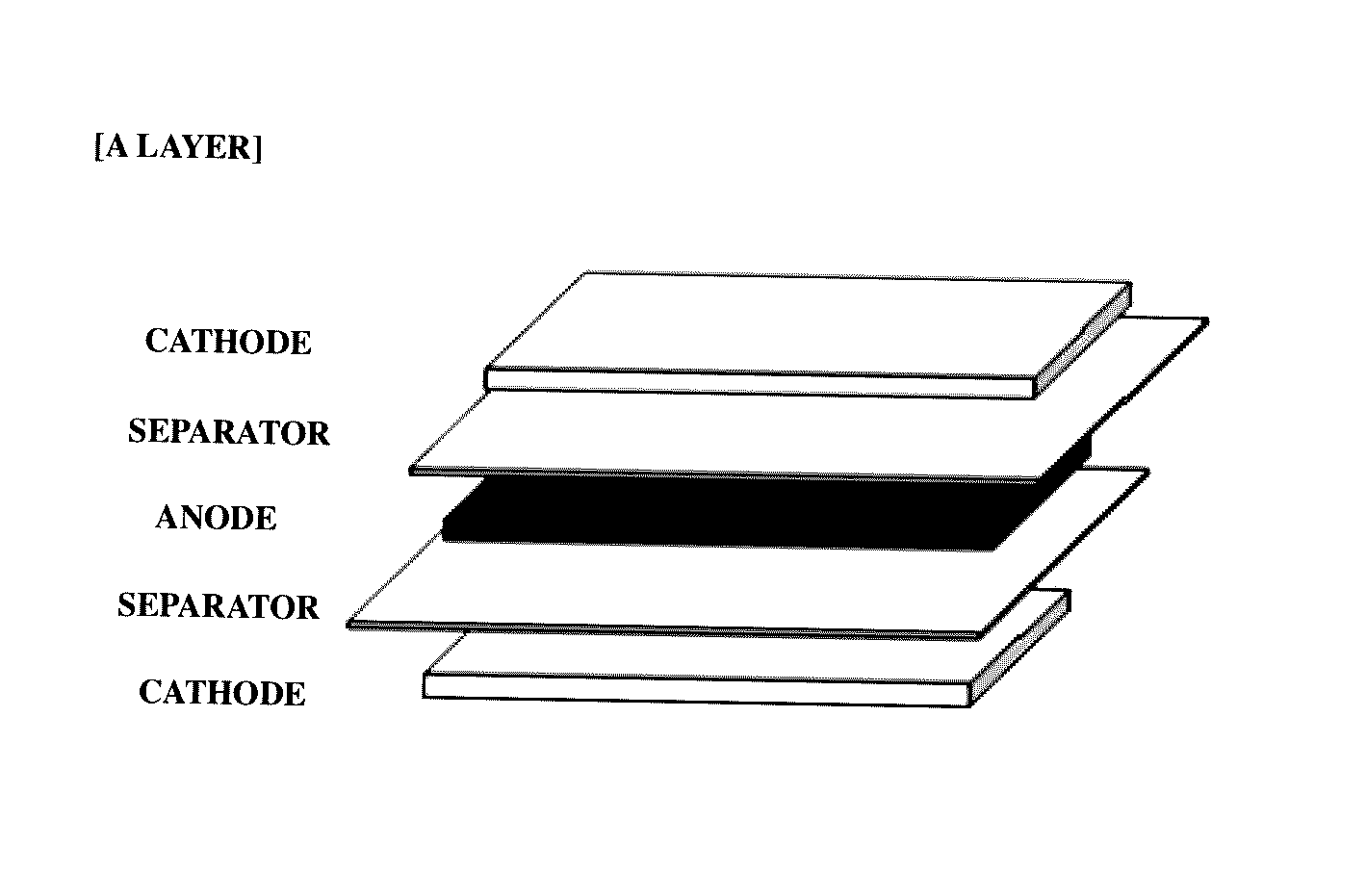
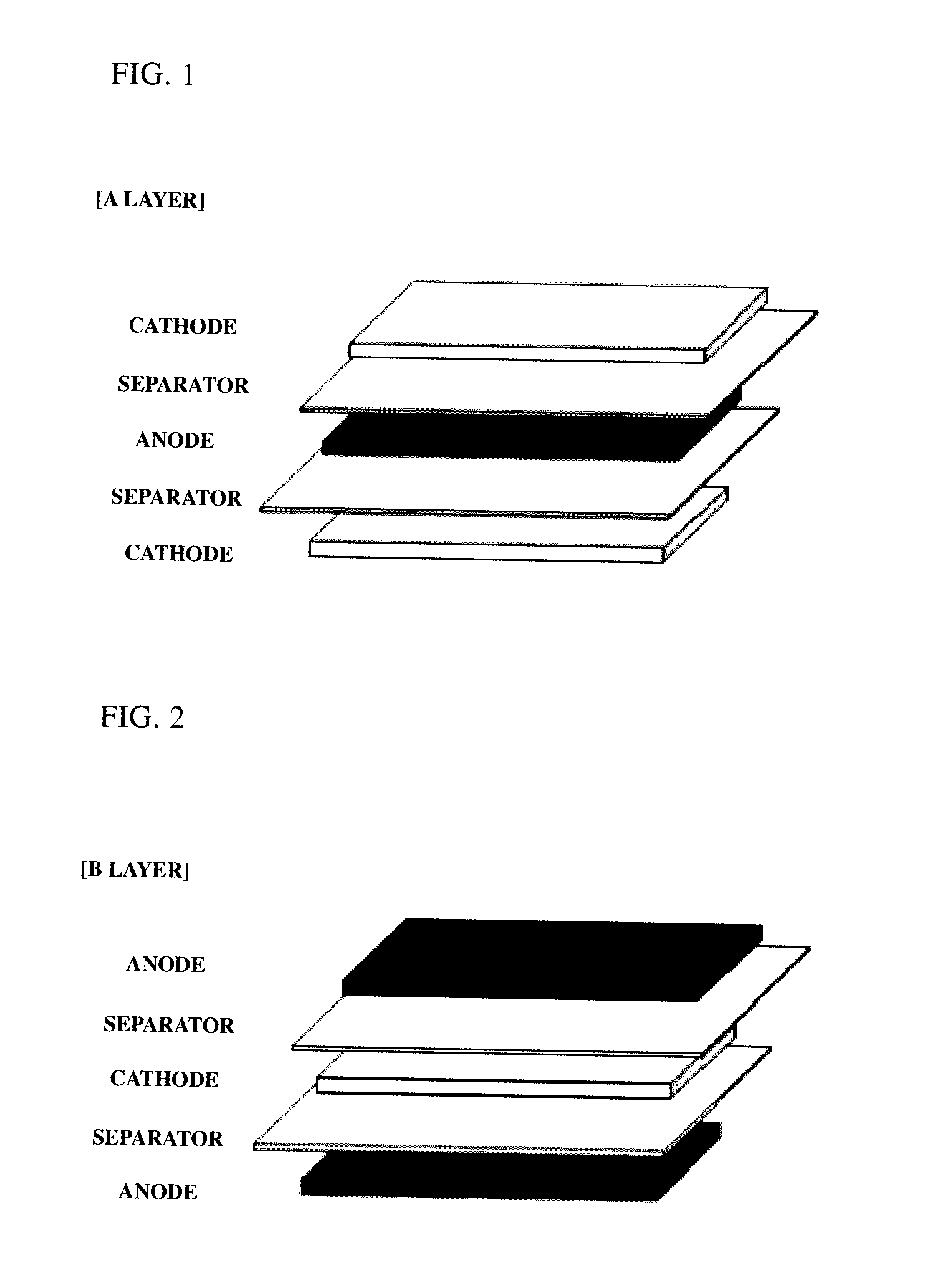
[0072]By interposing separators (thickness: 20 μm) between the prepared cathodes and anodes, a plurality of A-type bicells (see FIG. 1) having a unit stacked structure of cathode / separator / anode / separator / cathode and a plurality of C-type bicells having a unit stacked struc...

experimental example 1

[0075]Cut-off voltages of the secondary batteries manufactured according to Example 1 and Comparative Example 1 were set to 3.5 V and anode and cathode potentials of each secondary battery were measured when the cut-off voltage was reached. Results are shown in Table 1 below.

[0076]

TABLE 1Anode potential (V)Cathode potential (V)Example 11.264.76Comparative1.55.0Example 1

[0077]Referring to Table 1, in the secondary battery of Example 1, the potential of the anode is 1.26 V when the cut-off voltage is reached and thus the potential of the cathode is 4.76 V and, accordingly, the potential of the cathode reaches the cut-off voltage before reaching an oxidation potential of an electrolyte. By contrast, in the secondary battery of Comparative Example 1, the potential of the anode is 1.5 V when the cut-off voltage is reached and thus the potential of the cathode is 5.0V and thus reaches an oxidation potential of an electrolyte.

experimental example 2

Evaluation of Lifespan Characteristics of Secondary Battery

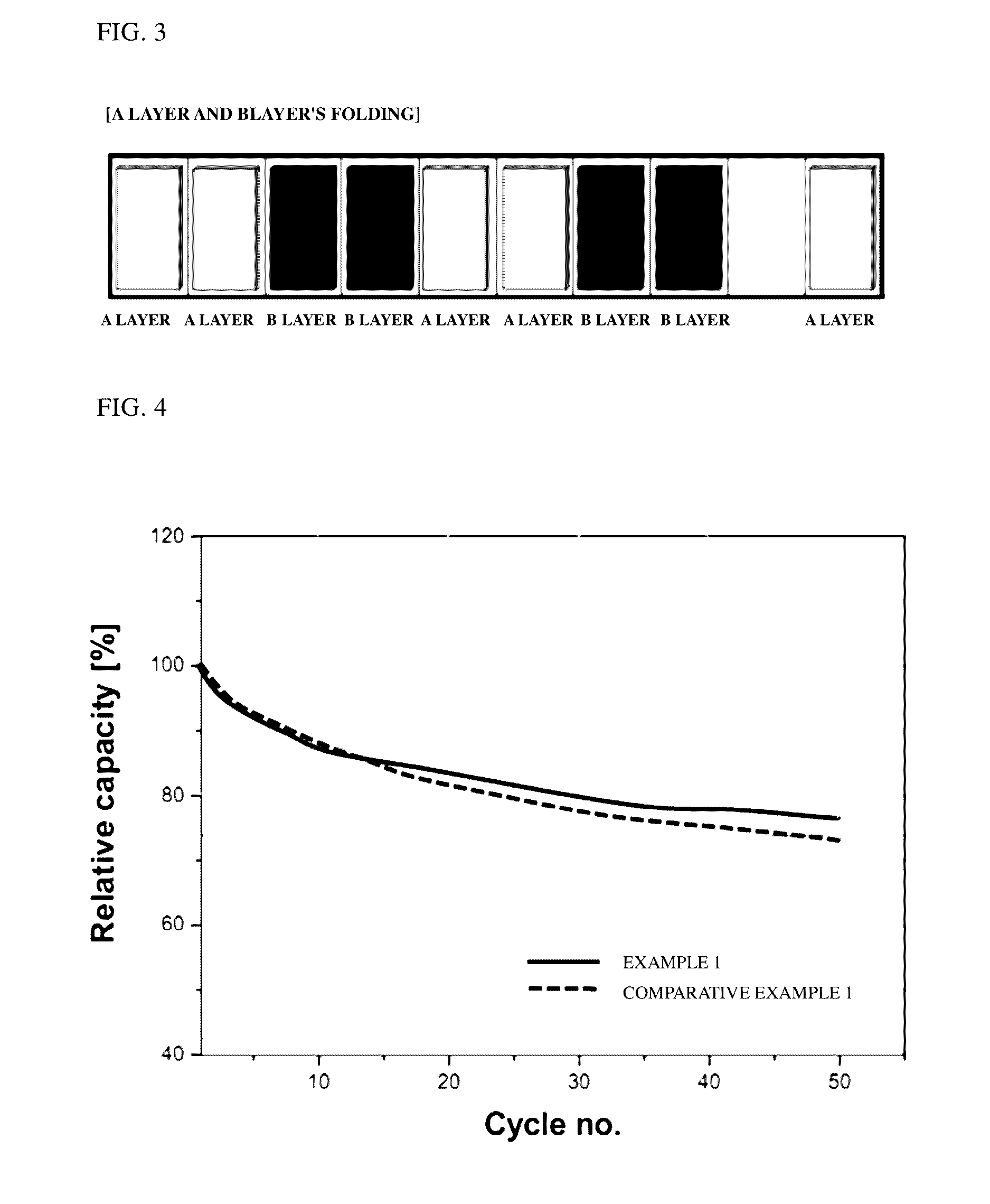
[0078]The secondary batteries of Example 1 and Comparative Example 1 were subjected to charging and discharging at 1 C and 600 mA in a range of 2 to 3.35 V. Changes in charge capacity of each battery were measured while 50 charging and discharging cycles were repeated at room temperature. Results are shown in FIG. 4.

[0079]Referring to FIG. 4, the secondary battery of Example 1 exhibits a capacity retention ratio of approximately 77%, while the secondary battery of Comparative Example 1 exhibits a capacity retention ratio of approximately 72%. From the results, it can be confirmed that the battery of Example 1 exhibits less reduction in charge capacity than that of the battery of Comparative Example 1 even when charging and discharging processes are repeated.


PUM

PropertyMeasurementUnit
charge cut-off voltageaaaaaaaaaa

Abstract

Disclosed is a lithium secondary battery including an electrode assembly including a cathode, an anode, and a separator disposed between the cathode and the anode and an electrolyte, wherein the cathode includes a spinel-structure lithium manganese composite oxide represented by Formula 1 below as a cathode active material, and the lithium secondary battery has a charge cut-off voltage of 3.3 to 4 V and, when the charge cut-off voltage is reached, the anode has a potential of 0.75 to 1.545 V within a range within which a potential of the cathode does not exceed 4.95 V:LixMyMn2−yO4−zAz  (1)wherein 0.9≦x≦1.2, 0<y<2, and 0≦z<0.2;M is at least one element selected from the group consisting of Al, Mg, Ni, Co, Fe, Cr, V, Ti, Cu, B, Ca, Zn, Zr, Nb, Mo, Sr, Sb, W, Ti, and Bi; andA is at least one monovalent or divalent anion.

Description

CROSS-REFERENCE TO RELATED APPLICATIONS[0001]The present application is a continuation of International Patent Application No. PCT / KR2013 / 003258, filed Apr. 17, 2013, which claims the priority from Korean Application No. 10-2012-0039450, filed Apr. 17, 2012, in the Korean Intellectual Property Office, the disclosures of which are incorporated herein by reference.TECHNICAL FIELD[0002]The present invention relates to a lithium secondary battery with excellent performance and, more particularly, to a lithium secondary battery including: an electrode assembly including a cathode, an anode, and a separator disposed between the cathode and the anode; and an electrolyte, wherein the cathode includes a spinel-structure lithium manganese composite oxide represented by a particular chemical formula as a cathode active material, the lithium secondary battery has a charge cut-off voltage of 3.3 to 4 V, and, when the charge cut-off voltage is reached, the anode has a potential of 0.75 to 1.545 V...

Claims


Application Information

Patent Timeline
Patent Type & Authority Patents(United States)
IPC IPC(8): H01M4/505H01M10/058H01M10/04H01M4/525H01M4/485H01M10/052H01M10/0585H01M10/42
CPCH01M4/505H01M4/485H01M4/525H01M10/045H01M10/0413H01M10/0431H01M10/052H01M10/058H01M10/0585H01M2010/4292H01M2220/20Y02E60/122Y02T10/7011Y02E60/10Y02P70/50H01M10/0525H01M10/0583H01M10/0587H01M2220/10H01M4/131Y02T10/70
Inventor LIM, SOO HYUNLEE, JAE HYUNLEE, YOUN KYOUNG
Owner LG ENERGY SOLUTION LTD
Learn More