
Liquid discharge apparatus, head unit, capacitive load drive circuit, and integrated circuit device for capacitive load drive

a capacitive load and liquid discharge technology, applied in logic circuits, logic circuit coupling/interface arrangements, pulse techniques, etc., can solve the problems of large switching loss, poor energy efficiency, and the feature of being likely to be affected by various types of noises, and achieve high accuracy and suppress the effect of nois

Active Publication Date: 2017-01-24
SEIKO EPSON CORP
View PDF7 Cites 4 Cited by
  • Summary
  • Abstract
  • Description
  • Claims
  • Application Information

AI Technical Summary

Benefits of technology

The invention provides a liquid discharge apparatus, head unit, capacitive load drive circuit, and integrated circuit device for capacitive load drive that can improve discharge accuracy of a liquid. The invention separates the adder and signal level conversion portion from other circuits by the triple-well structure to reduce parasitic capacitance and suppress noise interference. The high-frequency feedback signal helps generate accurate modulation signals and control the voltage applied to the piezoelectric element, resulting in improved discharge accuracy. Additionally, the invention addresses issues related to waveform dullness and discharge failure to ensure high-quality printing and superior performance.

Problems solved by technology

As an amplification circuit, a system of performing the current amplification of a source signal before the amplification by a Class AB amplifier or the like is used, but since energy efficiency is poor, a Class D amplifier is offered in recent years (see JP-A-2010-114711).
However, there is a feature of being likely to be affected by various types of noises due to the high oscillation frequency.
However, since a switching frequency is climbed in the transistor, a switching loss becomes large, and power saving properties and heating saving properties which have predominance in comparison with a linear amplification such as a Class AB amplifier, are damaged.

Method used


Image

  • Liquid discharge apparatus, head unit, capacitive load drive circuit, and integrated circuit device for capacitive load drive
  • Liquid discharge apparatus, head unit, capacitive load drive circuit, and integrated circuit device for capacitive load drive
  • Liquid discharge apparatus, head unit, capacitive load drive circuit, and integrated circuit device for capacitive load drive

Examples


Embodiment Construction

[0043]Hereinafter, suitable embodiments of the invention will be described in detail by using drawings. The used drawings are for convenience of the description. Furthermore, the embodiments described below do not unjustly limit the contents of the invention which are written in the scope of the claims. Moreover, all of configurations which are described below are not necessarily to be compulsory configuration components of the invention.

1. Outline of Liquid Discharge Apparatus

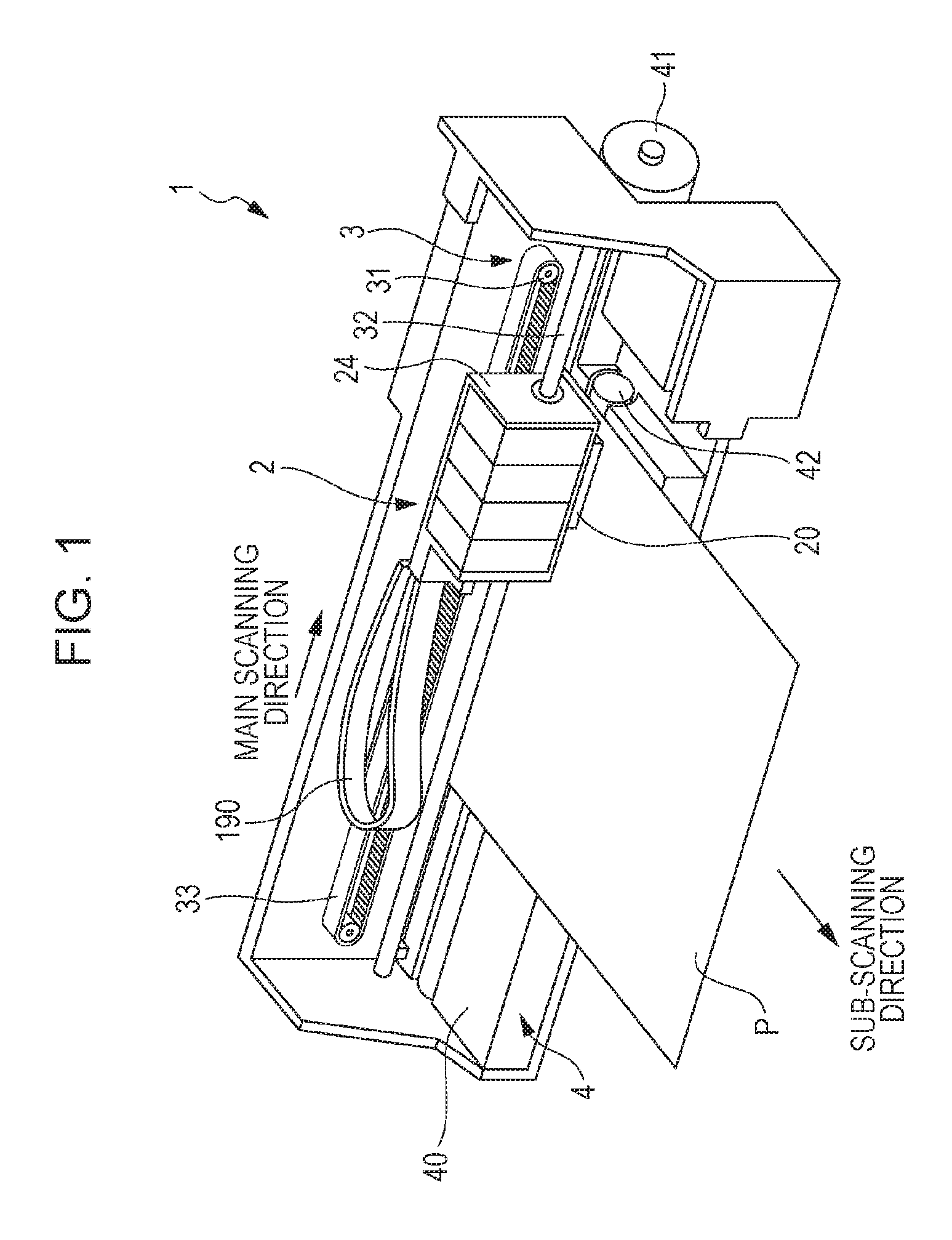
[0044]A printing apparatus as an example of a liquid discharge apparatus according to the embodiment, is an ink jet printer that forms an ink dot group on a printing medium such as paper by discharging an ink in accordance with image data which is supplied from an external host computer, and prints an image (including a character, a figure or the like) in accordance with the image data.

[0045]As a liquid discharge apparatus, for example, it is possible to use a printing apparatus such as a printer, a color mate...


PUM


Abstract

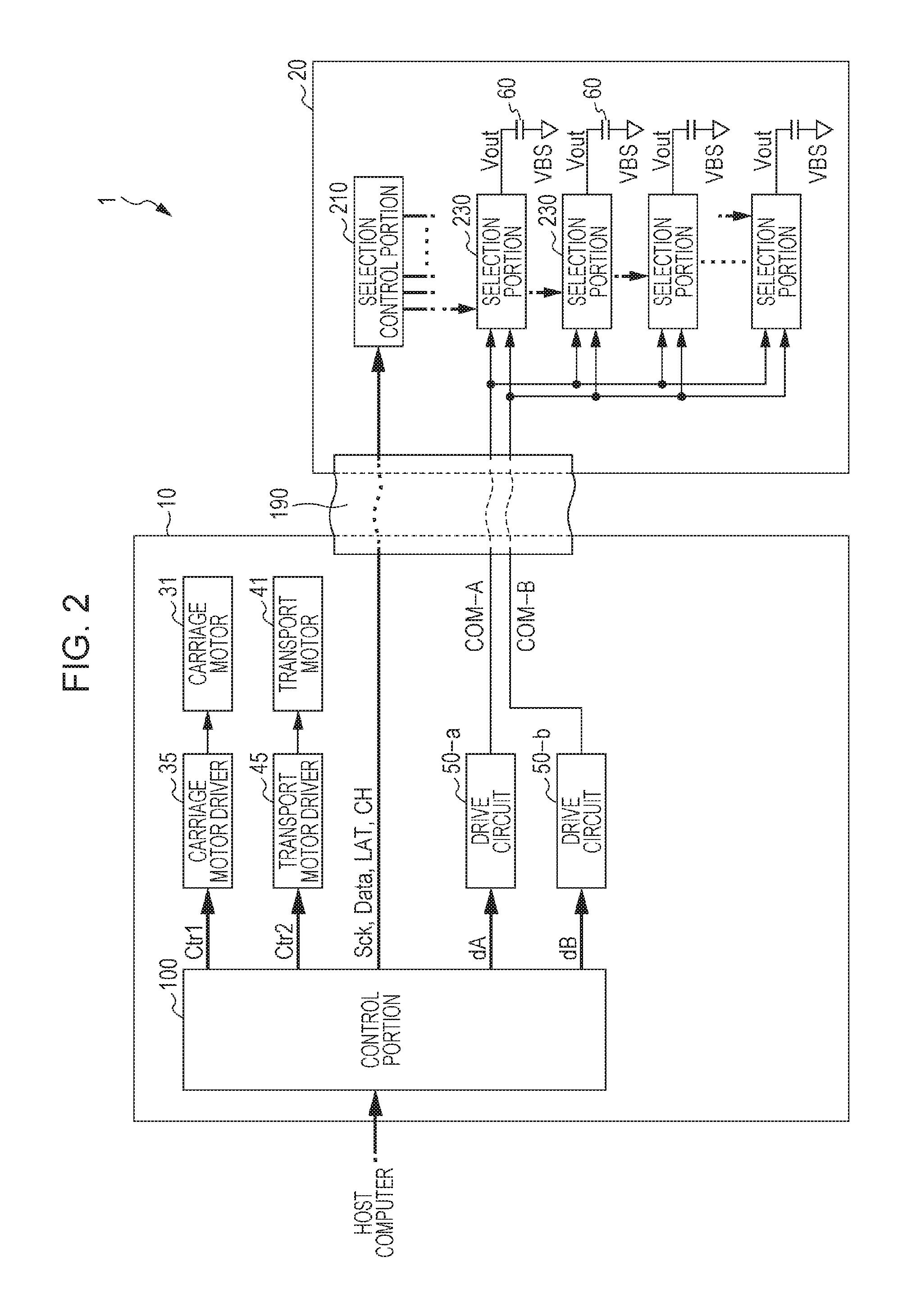
A liquid discharge apparatus includes: an integrated circuit device that includes a modulation portion which generates a modulation signal by pulse-modulating a source signal; a feedback circuit; a transistor that generates an amplified modulation signal which is obtained by amplifying the modulation signal; a low-pass filter that generates a drive signal by demodulating the amplified modulation signal; and a piezoelectric element that is displaced by applying the drive signal, wherein the feedback circuit generates a feedback signal on the basis of the drive signal, and feeds back the feedback signal to the modulation portion through a feedback terminal, the modulation portion includes a first circuit block and a second circuit block, and the integrated circuit device is configured to separate the first circuit block from the second circuit block by a triple-well structure.

Description

[0001]The entire disclosure of Japanese Patent Application No. 2015-014095, filed Jan. 28, 2015 is expressly incorporated by reference herein.BACKGROUND[0002]1. Technical Field[0003]The present invention relates to a liquid discharge apparatus, a head unit, a capacitive load drive circuit, and an integrated circuit device for capacitive load drive.[0004]2. Related Art[0005]In a liquid discharge apparatus such as an ink jet printer which prints an image or a document by discharging an ink, a liquid discharge apparatus using a piezoelectric element (for example, a piezo element) is known. The piezoelectric elements are respectively arranged by correlating with a plurality of nozzles in a head unit, and each thereof are driven in accordance with a drive signal. Thereby, a predetermined amount of the ink (liquid) is discharged at a predetermined timing from the nozzle, and dots are formed. Since the piezoelectric element is a capacitive load such as a capacitor if being electrically vie...

Claims


Application Information

Patent Timeline
Patent Type & Authority Patents(United States)
IPC IPC(8): H03K19/0185B41J2/045
CPCB41J2/04541B41J2/04573B41J2/04581B41J2/04588H03K19/018507B41J2/04586
Inventor SHIMA, SHUNICHI
Owner SEIKO EPSON CORP
Learn More