
Start-up method of hydrocarbon synthesis reaction apparatus

a hydrocarbon synthesis and reaction apparatus technology, applied in the field of hydrocarbon synthesis reaction apparatus start-up method, can solve problems such as thermal degradation of catalysts, and achieve the effects of reducing feedstock loss, improving economic performance of plants, and shortening the start-up time of hydrocarbon synthesis reaction apparatus

Active Publication Date: 2016-08-02
JAPAN OIL GAS & METALS NAT CORP +5
View PDF8 Cites 0 Cited by
  • Summary
  • Abstract
  • Description
  • Claims
  • Application Information

AI Technical Summary

Benefits of technology

[0029]According to the present invention, it is possible to shorten the start-up time of a hydrocarbon synthesis reaction apparatus and to reduce loss of the feedstock during the start-up of a hydrocarbon synthesis reaction apparatus. Hence, it is possible to improve the economic performance of a plant and prevent thermal deterioration of the catalyst particles caused by an increase in the temperature of the slurry.
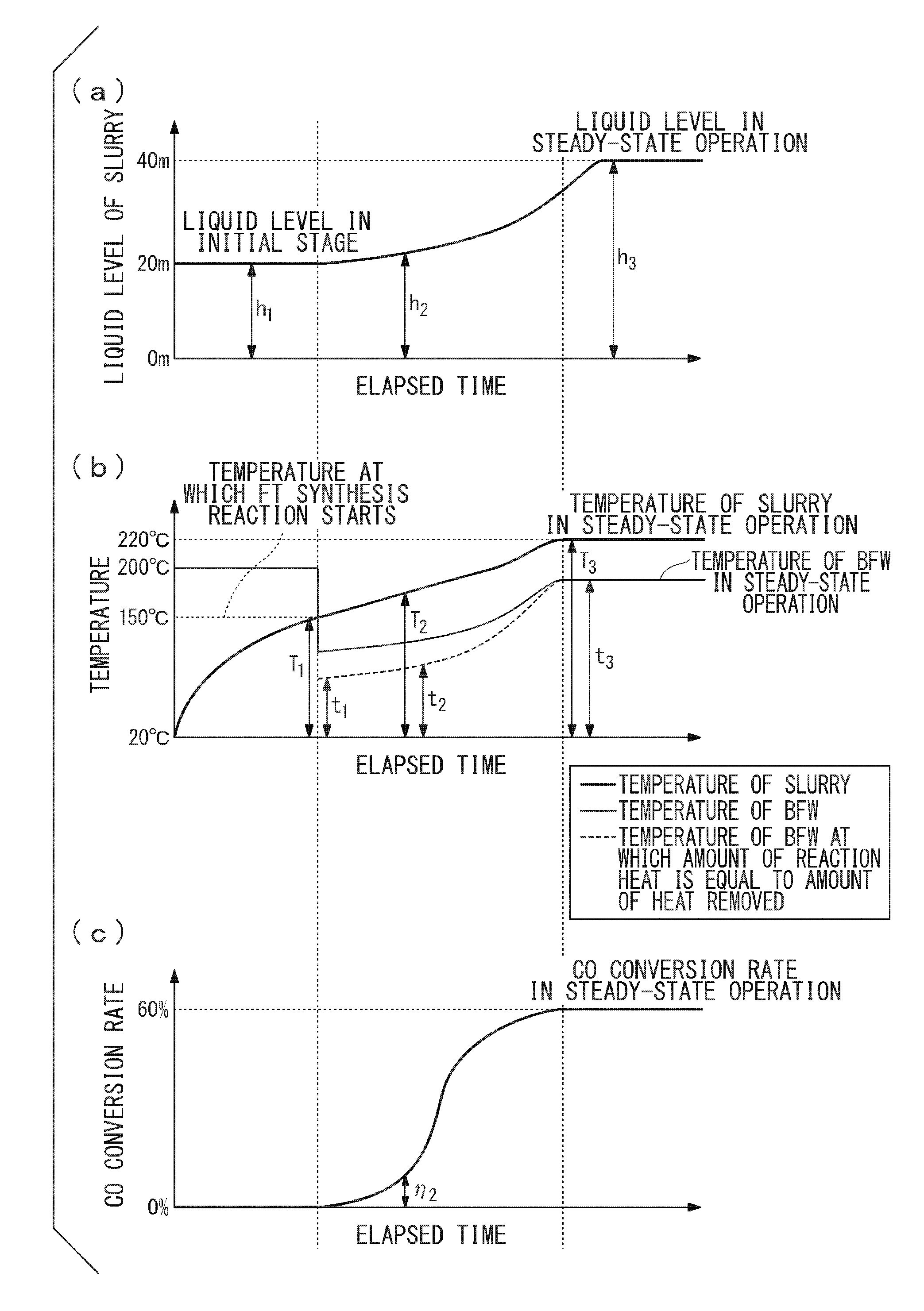
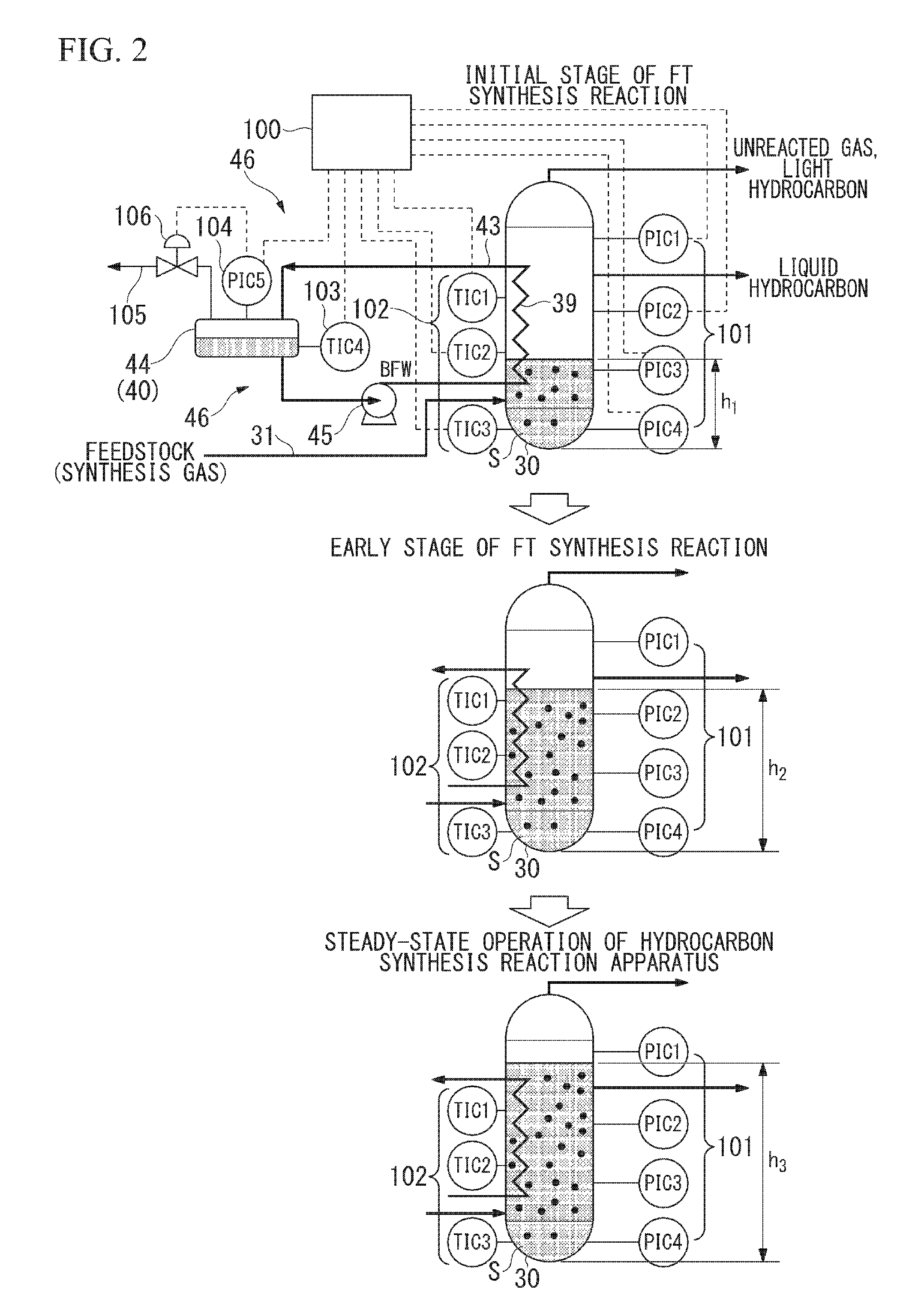
[0030]According to the present invention, the temperature of the slurry is controlled in proportion to the rise in the liquid level of the slurry; that is, in consideration of the cooling capacity of the heat exchanger tube. Therefore, it is possible to suppress the rapid increase in the temperature caused by heat generated in the slurry by the FT synthesis reaction, and the CO conversion ratio can increase.
[0031]According to the present invention, since the temperature of the coolant flowing through the heat exchanger tube is controlled, it is possible to control the temperature of the slurry in contact with the heat exchanger tube to be the predetermined temperature. Therefore, it is possible to suppress the rapid increase in the temperature of the slurry caused by heat generated in the slurry by the FT synthesis reaction, and the CO conversion ratio can be increased efficiently.
[0032]According to the present invention, it is possible to accelerate FT synthesis reaction efficiently, by maintaining the temperature of the slurry in the range of 150° C. to 240° C.

Problems solved by technology

In the case in which heat generated by the reaction is not removed, the temperature in the reactor increases rapidly by accelerating FT synthesis reaction, thereby causing thermal deterioration of the catalyst.

Method used


Image

  • Start-up method of hydrocarbon synthesis reaction apparatus
  • Start-up method of hydrocarbon synthesis reaction apparatus
  • Start-up method of hydrocarbon synthesis reaction apparatus

Examples


Embodiment Construction

[0038]Hereinafter, a description will be given of one embodiment of the hydrocarbon synthesis reaction system including the hydrocarbon synthesis reaction apparatus of the present invention with reference to the drawings.

(Liquid Fuel Synthesizing System)

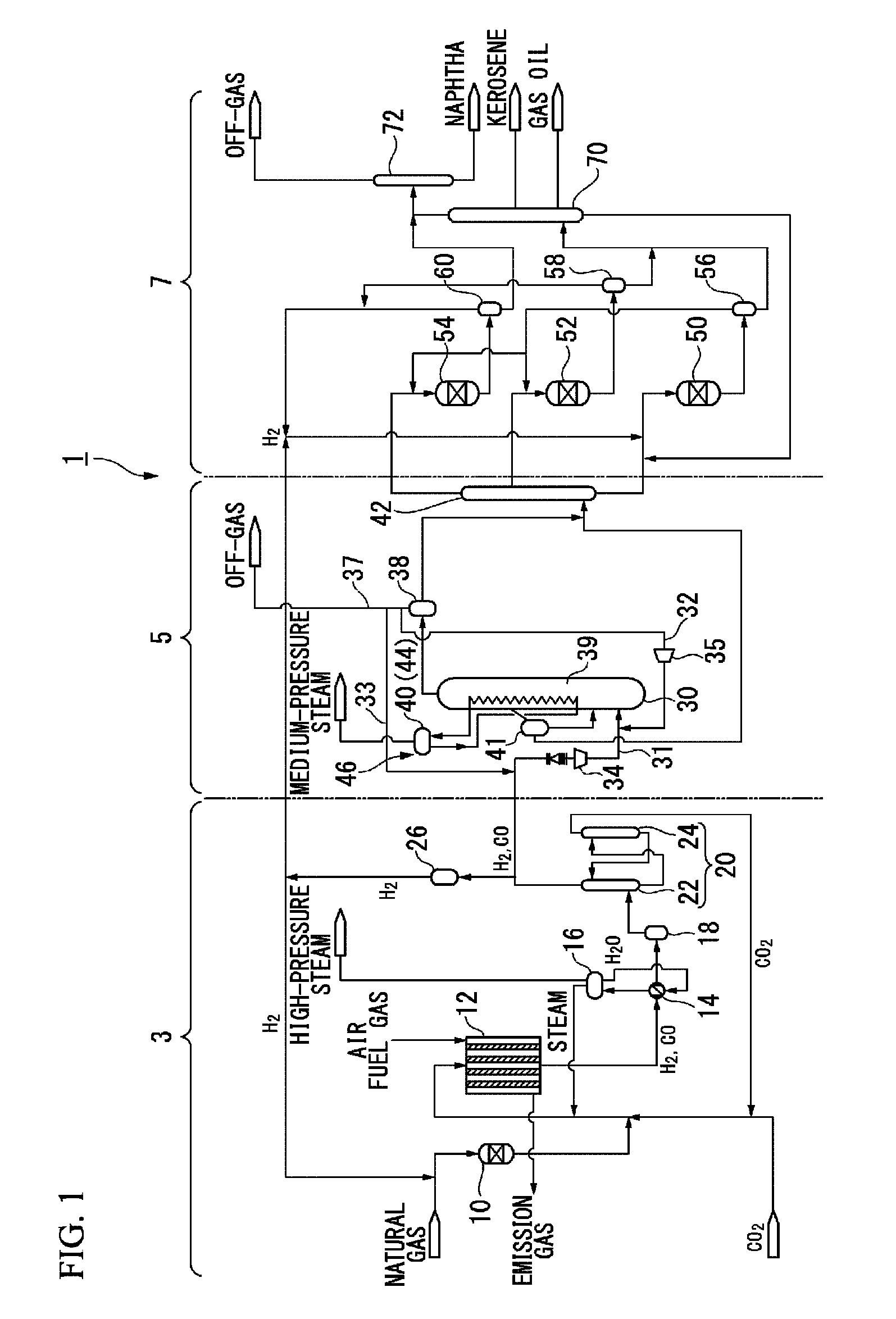
[0039]FIG. 1 is a systematic diagram showing the structure of a liquid fuel synthesizing system used for carrying out an embodiment of a start-up method for a hydrocarbon synthesis reaction apparatus of the present invention.

[0040]As illustrated in FIG. 1, the liquid fuel synthesizing system (hydrocarbon synthesis reaction system) 1 is a plant facility which carries out a GTL process that converts a hydrocarbon feedstock such as a natural gas into liquid fuels. This liquid fuel synthesizing system 1 includes a synthesis gas production unit 3, an FT synthesis unit (hydrocarbon synthesis reaction apparatus) 5, and an upgrading unit 7. The synthesis gas production unit 3 configured to reform a natural gas that functions as a hydrocarbon...


PUM

PropertyMeasurementUnit
temperatureaaaaaaaaaa

Abstract

A start-up method for a hydrocarbon synthesis reaction apparatus, comprising: an initial slurry-loading step in which the slurry is loaded into the reactor at the initial stage of the Fischer-Tropsch synthesis reaction at a lower loading rate than that applied to the reactor in a steady-state operation; and a CO conversion ratio-increasing step in which the liquid level of the slurry in the reactor is raised by adding to the slurry the hydrocarbons synthesized at the early stage of the Fischer-Tropsch synthesis reaction so that the CO conversion ratio is increased in proportion to a rise in the liquid level of the slurry in the reactor.

Description

CROSS-REFERENCE TO RELATED APPLICATION[0001]This application is a Section 371 of International Application No. PCT / JP2013 / 080027, filed Nov. 6, 2013, which was published in the Japanese language on May 15, 2014, under International Publication No. WO 2014 / 073575 A1, the disclosure of which is incorporated herein by reference.BACKGROUND OF THE INVENTION[0002]1. Field of the Invention[0003]The present invention relates to a start-up method of a hydrocarbon synthesis reaction apparatus.[0004]Priority is claimed on Japanese Patent Application No. 2012-247727 filed on Nov. 9, 2012, the content of which is incorporated herein by reference.[0005]2. Description of Related Art[0006]In recent years, as a process for synthesizing liquid fuels from natural gas, the GTL (gas-to-liquids: liquid fuels synthesis) technique has been developed. This GTL technique includes the steps of reforming a natural gas to produce a synthesis gas containing carbon monoxide gas (CO) and hydrogen gas (H2) as main ...

Claims


Application Information

Patent Timeline
Patent Type & Authority Patents(United States)
IPC IPC(8): C07C27/00C10G2/00
CPCC10G2/344C10G2/342C10G2/32C10G2300/4031
Inventor ITO, TAKEOMURATA, ATSUSHIYAMADA, EIICHIKATO, YUZURUONISHI, YASUHIRO
Owner JAPAN OIL GAS & METALS NAT CORP
Learn More