
Fast start-up crystal oscillator

a crystal oscillator and fast technology, applied in the field of crystal oscillators, can solve the problems of speeding up the stabilization of oscillations, and achieve the effects of reducing the start-up time of crystal oscillators, increasing and reducing the negative resistance of the gain stag

Active Publication Date: 2011-02-17
TEXAS INSTR INC
View PDF12 Cites 40 Cited by
  • Summary
  • Abstract
  • Description
  • Claims
  • Application Information

AI Technical Summary

Benefits of technology

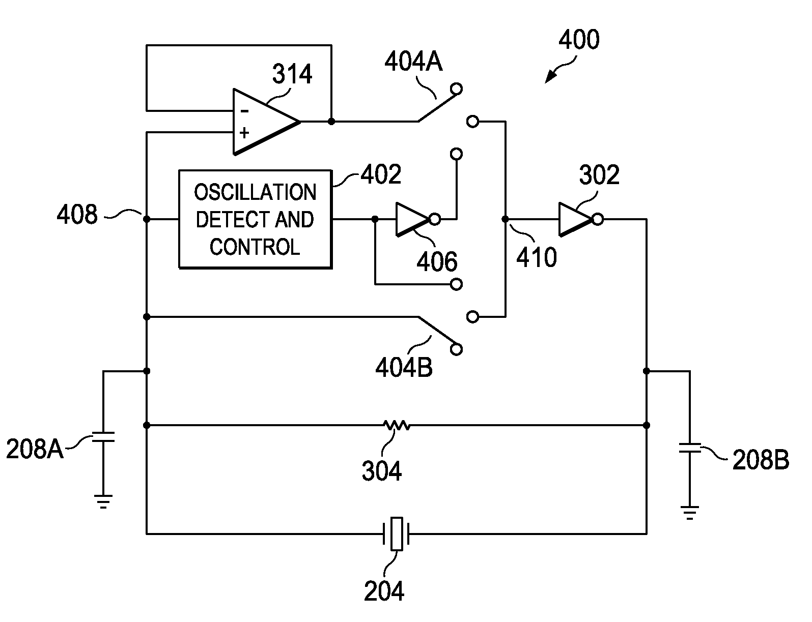
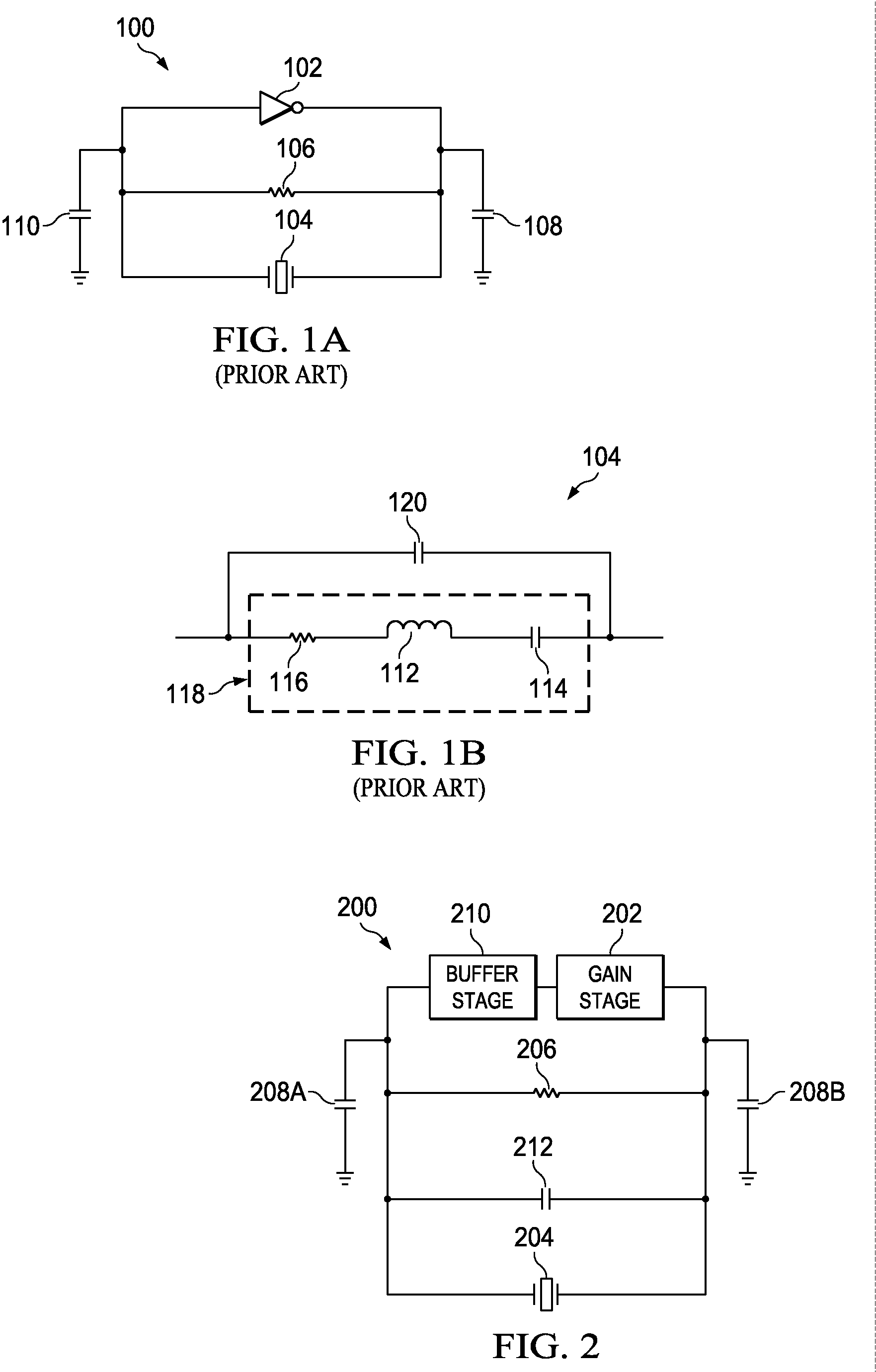
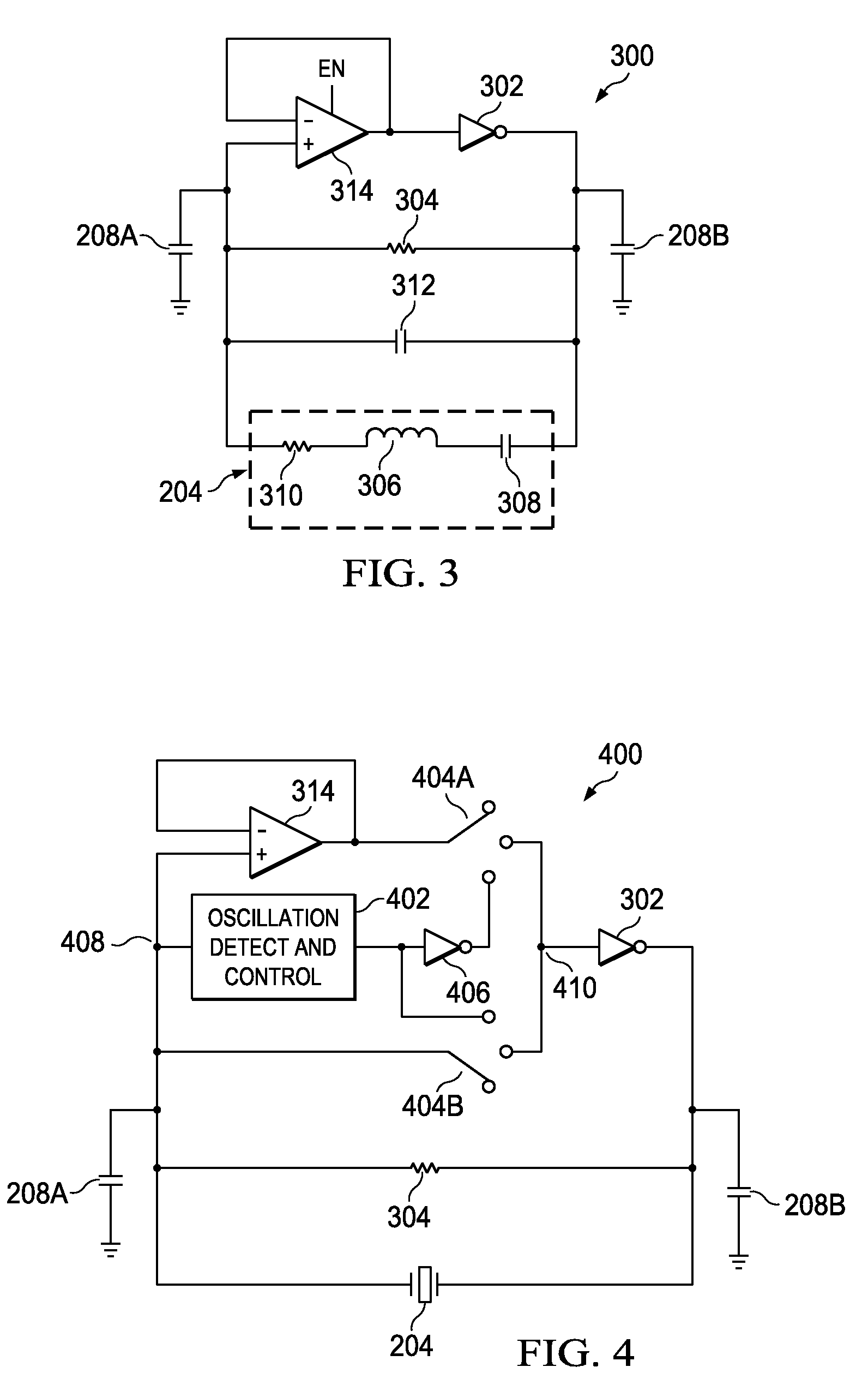
Embodiments of the invention are directed to an exemplary system and method for reducing the start-up time of crystal oscillators. The exemplary fast start-up crystal oscillator includes a gain stage with negative resistance. A crystal is operatively coupled in the feedback loop of the gain stage. The crystal includes a shunt capacitance. In addition, a buffer is coupled to the gain stage of the crystal oscillator such that the buffer can isolate the gain stage from the crystal shunt capacitance and effectively increase the negative resistance of the gain stage. An increase in the negative resistance increases the rate of growth of an oscillation signal in the oscillator, thereby reducing the start-up time.

Problems solved by technology

Reaching the bias point faster ensures that oscillations start quickly but does not speed-up the stabilization of oscillations in any manner.

Method used


Image

  • Fast start-up crystal oscillator
  • Fast start-up crystal oscillator
  • Fast start-up crystal oscillator

Examples


Embodiment Construction

The following detailed description is made with reference to the figures. Preferred embodiments are described to illustrate the present invention, not to limit its scope, which is defined by the claims. Those of ordinary skill in the art will recognize a variety of equivalent variations of the description that follows.

Overview

FIG. 1 includes FIG. 1(a) that depicts a typical crystal oscillator 100, together with FIG. 1(b) that depicts a well-known equivalent circuit diagram of a crystal. FIG. 1 is used to explain the operation of a typical crystal oscillator 100 to assist understanding the operation of the exemplary crystal oscillator of the claimed invention. The crystal oscillator 100 includes an amplifier 102 with a crystal 104 in a feedback loop. The amplifier 102 can be an inverting amplifier. A biasing resistor 106 is connected in parallel with the amplifier 102 for biasing the amplifier 102 in its negative resistance range. The crystal oscillator 100 further includes load capa...


PUM


Abstract

An exemplary fast start-up crystal oscillator with reduced start-up time. The exemplary oscillator reduces the start-up time (i.e., the time taken to attain sustained stable oscillations after the power is turned on) by increasing the negative resistance of a circuit. Increasing the negative resistance increases the rate of growth of the oscillations, thereby reducing start-up time. The exemplary crystal oscillator includes a gain stage with negative resistance. A crystal with shunt capacitance is placed in the feedback loop of the gain stage. A buffer is coupled to the gain stage such that it blocks the crystal shunt capacitance from loading the gain stage, effectively increasing the negative resistance of the gain stage. Further, an oscillation detection and control circuit is coupled between the crystal and the gain stage. The oscillation detection and control circuit connects the buffer during start-up, and disconnects the buffer once an oscillation signal attains sustained stable oscillations.

Description

TECHNICAL FIELDEmbodiments of the present invention relate to crystal oscillators and more specifically to fast start-up crystal oscillators.BACKGROUNDMost digital circuits use oscillators to provide clocking for synchronous digital devices. A wide range of oscillators, for different applications, are available that provide highly accurate and frequency-selective signals. One category of oscillators is crystal oscillators, which employ vibrating crystals to create electrical signals with very precise frequencies. These oscillators typically provide a stable clock signal to stabilize frequencies for radio transmitters / receivers and for digital integrated circuits.Crystal oscillators commonly include an amplifier and a crystal in the amplifier's feedback loop. In certain applications, such as mobile phones, the crystal oscillator is frequently turned off when not in use, to save power. In these applications, it is essential that the crystal oscillator achieve stable oscillations quick...

Claims


Application Information

Patent Timeline
Patent Type & Authority Applications(United States)
IPC IPC(8): H03B5/30
CPCH03B2200/0094H03B5/06
Inventor SHRIVASTAVA, AATMESHYADAV, RAJESHRANA, PARVINDER KUMAR
Owner TEXAS INSTR INC
Learn More