
Cutting tool for boring

a cutting tool and boring technology, applied in the direction of wood boring tools, manufacturing tools, transportation and packaging, etc., can solve the problems of difficult to remove the chips produced in the cutting process, the performance of the chip control (removing) is degraded, and the problem of more serious problems, to achieve the effect of smooth removal of chips

Active Publication Date: 2016-04-12
NGK SPARK PLUG CO LTD
View PDF14 Cites 4 Cited by
  • Summary
  • Abstract
  • Description
  • Claims
  • Application Information

AI Technical Summary

Benefits of technology

The invention is aimed at solving problems in the prior art by providing a cutting tool that can effectively remove chips smoothly without getting in the way during the cutting process. This is particularly useful when small-diameter and deep holes are being machined. The technical effect is improved chip removal efficiency.

Problems solved by technology

Therefore, the gap (space) between the inner circumferential surface of the hole and the outer circumferential surface of the holder becomes too small, such that it is difficult to remove the chips produced in the cutting process from the inlet of the hole of the workpiece at the rear end (base) of the holder (also called a shank) to the outside (rear end side of the holder).
Further, the deeper the hole in the cutting conditions, the more serious the problem becomes.
As the performance of the chip control (removing) degrades, the chips are easily stuck between the inner circumferential surface of the machined hole and the cutting edge or the holder.
Accordingly, the machined surface (inner circumferential surface) is damaged, and the machined surface is roughened.
Further, in some cases, machining is inevitably stopped in order to remove the chips.
This problem tends to occur in particular in an external oil supply type apparatus in which cutting oil is supplied from the outside, rather than in an internal oil supply type apparatus in which cutting oil is supplied from the front end of the holder.
However, simply thinning the holder causes chatter vibration due to a decrease in stiffness.

Method used


Image

  • Cutting tool for boring
  • Cutting tool for boring
  • Cutting tool for boring

Examples


third exemplary embodiment

[0076]Next, a cutting tool 301 for boring according to the present disclosure is described with reference to FIGS. 14 to 18. However, as described above, although the ridges of holder 10 are formed where the bottom surface 33 of the cutting surface-sided chip pocket 30 and the surface (bottom surface) 52 of the cutting edge-sided chip pocket 50 intersect (at the edge 35 of the portion of the outer circumferential surface where the cutting edge overhangs on the bottom surface 33 of the cutting surface-sided chip pocket 30) in the first and second exemplary embodiments, a chamfered portion 36 is formed on the ridge in a predetermined size and cross-sectional shape in the present exemplary embodiment (third exemplary embodiment). The present exemplary embodiment is not different from the first exemplary embodiment, except for the chamfered portion 36 on the ridge (edge 35). Therefore, only this difference is described. The same parts are designated by the same reference numerals and th...

fourth exemplary embodiment

[0080]FIG. 19 is a view showing an example (fourth exemplary embodiment) of a cutting tool 401 for boring having an inclined chamfered portion, as shown by the double hatch lines. The present exemplary embodiment is different from the third exemplary embodiment only in the shape and structure of the chamfered portions. Further, the same parts are designated by the same reference numerals, such that the detailed description is omitted. However, when chamfered portion 36 is an inclined chamfered portion as in the present exemplary embodiment, machining for forming the chamfered portion becomes easy. The inclined chamfered portion may be a 45 degree chamfered portion 36 formed by cutting the portion close to the end of the cutting surface (end edge 35 in the first exemplary embodiment) of the bottom surface 52 of the cutting edge-sided chip pocket 50, at an angle of 45 degrees with respect to the bottom surface 52. However, it may be formed at less than 45 degrees with respect to the b...


PUM

PropertyMeasurementUnit
outer diameteraaaaaaaaaa
diameteraaaaaaaaaa

Abstract

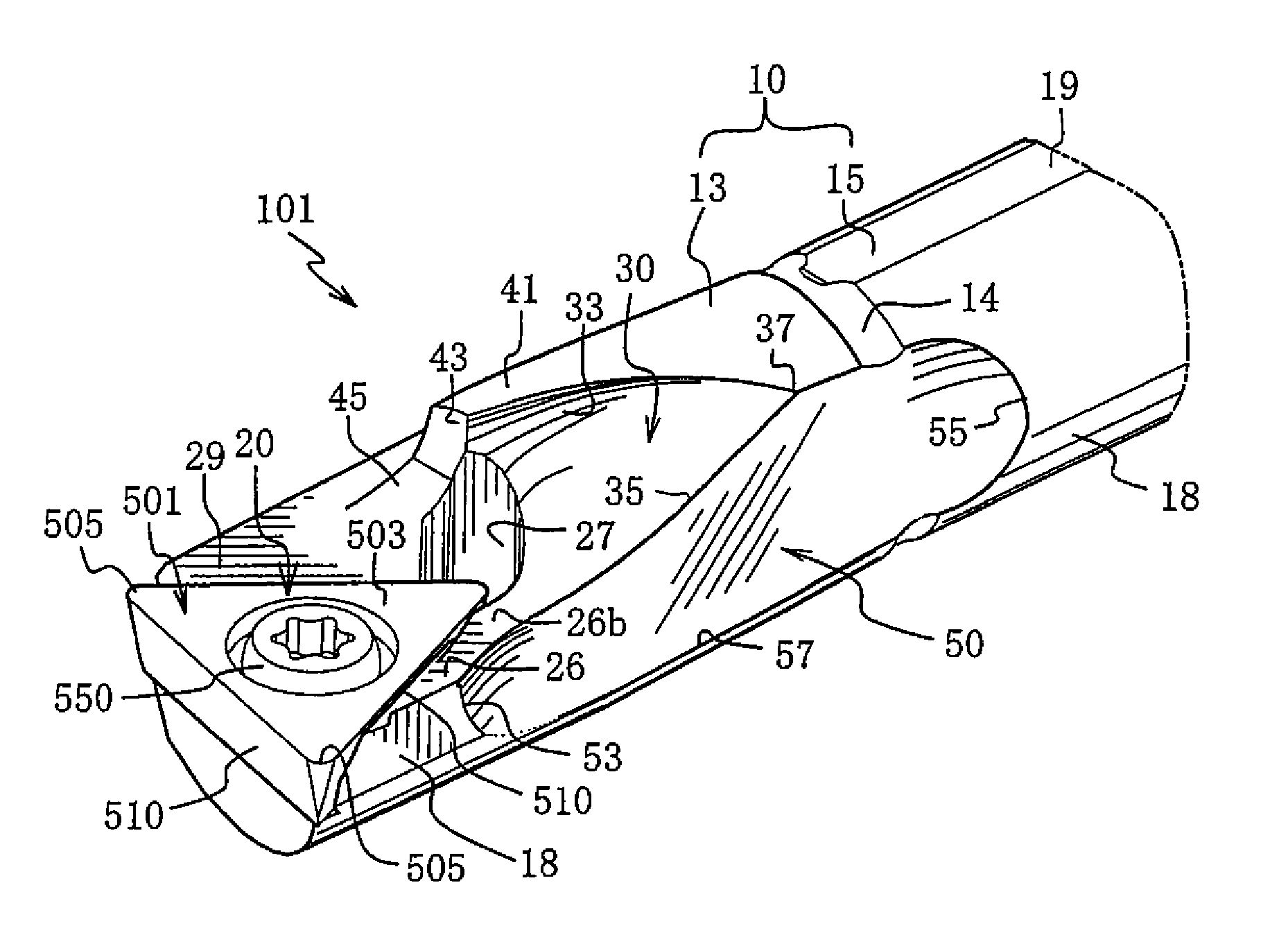
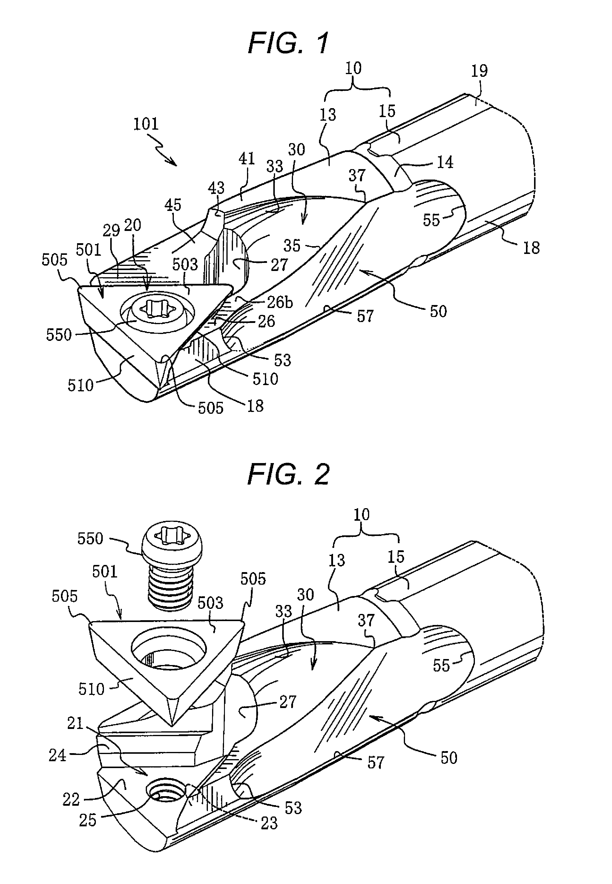
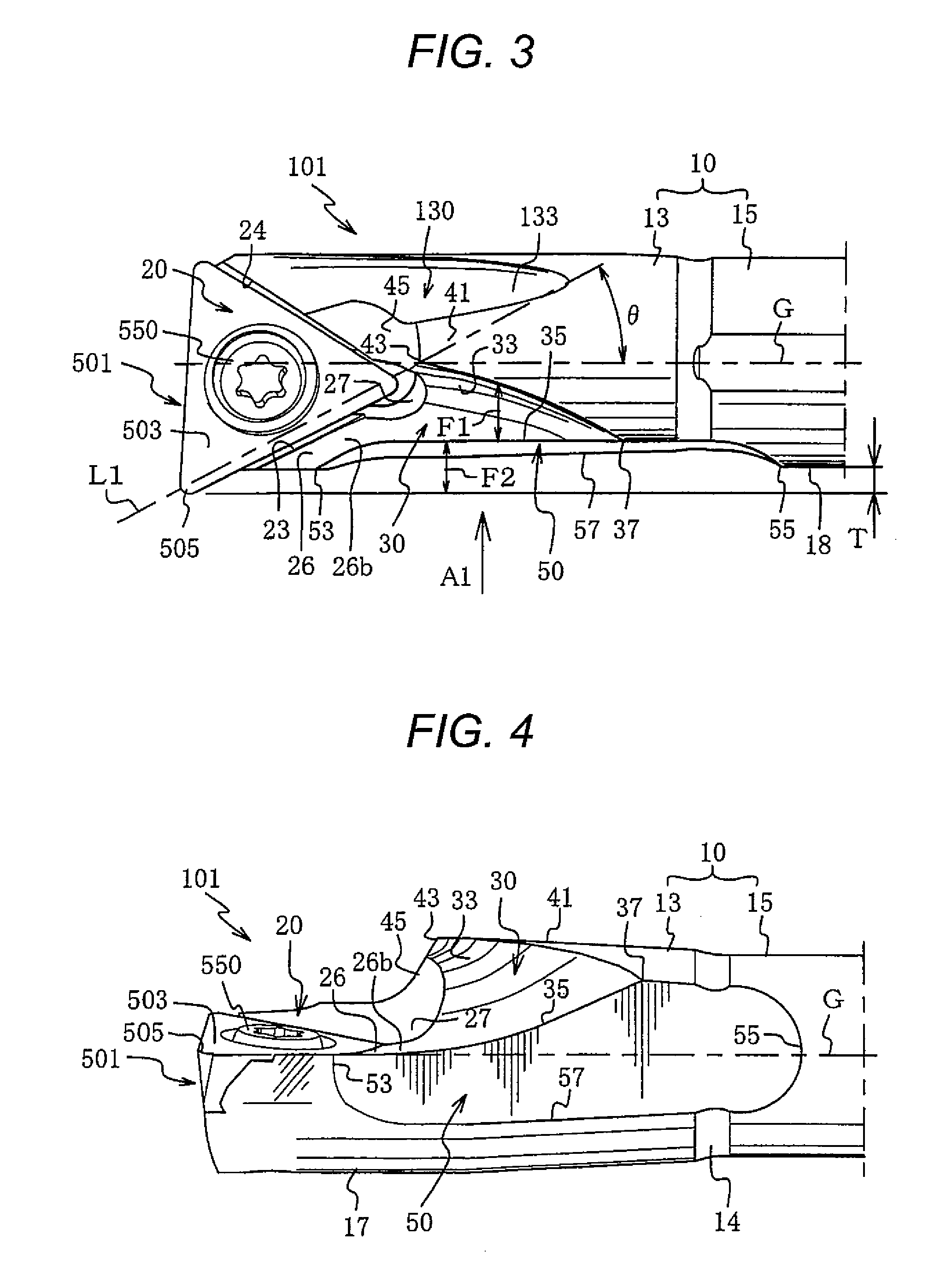
A cutting tool for boring including a cutting insert fixed at a front end of a bar-shaped holder. The holder includes a cutting surface-sided chip pocket that is concave with respect to the outer circumferential surface of the holder, the cutting edge end of the cutting insert protruding from the outer circumferential surface of the holder, and the cutting surface-sided chip pocket having a bottom surface facing the portion of outer circumferential surface where the cutting edge overhangs. Further, an cutting edge-sided chip pocket is formed at the portion of outer circumferential surface where the cutting edge overhangs such that the edge of the portion of outer circumferential surface where the cutting edge overhangs is concave with respect to the outer circumferential surface of the holder, on the bottom of the cutting surface-sided chip pocket when viewed from the cutting surface.

Description

BACKGROUND OF THE INVENTION[0001]1. Field of the Invention[0002]The present disclosure relates to a cutting tool for boring, and more particularly, to a cutting tool for boring (also called a boring bit) which is used for turning the inner circumferential surface of a hole having a circular cross-section, or the inner circumferential surface of a cylindrical pipe, particularly for machining a deep small-diameter hole.[0003]2. Description of the Related Art[0004]Cutting tools for boring are used to machine the inner circumferential surface of a hole of a workpiece (an object to be cut), such that the cutting edge (the front end of a cutting edge for cutting) of a cutting insert (for example, a throw-away type cutting insert) fixed to the front end of a bar-shaped holder overhangs from a side of the outer circumferential surface of the holder. In the cutting tool for boring (hereinafter, also referred to as a cutting tool), when the diameter of the inner circumferential surface of a h...

Claims


Application Information

Patent Timeline
Patent Type & Authority Patents(United States)
IPC IPC(8): B23B29/02B23B27/00
CPCB23B27/007B23B29/02B23B2270/30Y10T408/89Y10T408/892Y10T408/907B23B27/00B23B27/16B23B27/22
Inventor KITAGAWA, SHUSUKEISOBE, KENJI
Owner NGK SPARK PLUG CO LTD
Learn More