
Block copolymer blends

a copolymer blend and block technology, applied in the field of polymer structures, can solve the problems of uncontrollable cell-biomaterial interaction and cell response, unsatisfactory biological response, and limit the suitability of controlled attachment and subsequent growth of cells and tissues, so as to improve assay specificity and sensitivity, prevent non-specific interactions, and reduce cost

Active Publication Date: 2016-03-29
THE UNIV OF QUEENSLAND
View PDF9 Cites 0 Cited by
  • Summary
  • Abstract
  • Description
  • Claims
  • Application Information

AI Technical Summary

Benefits of technology

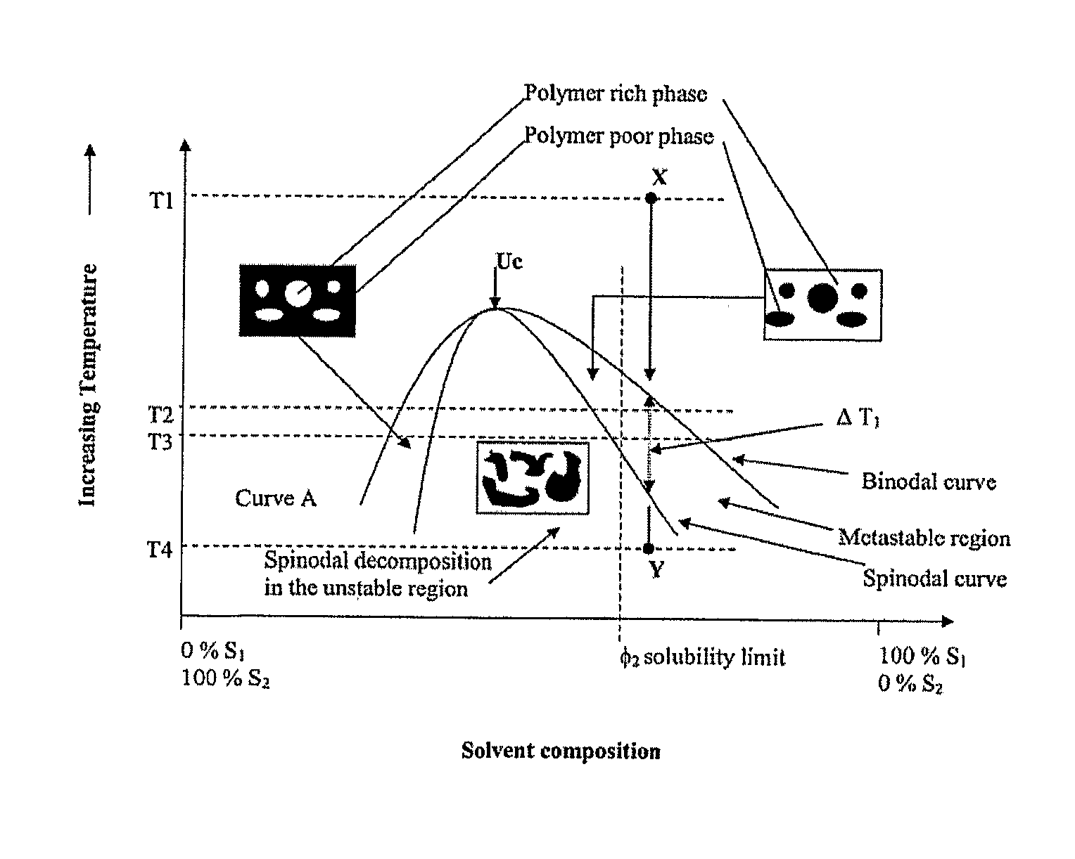
The present invention is a structure that can be applied to various supports such as tissue scaffolds, cell-culturing plastic-ware, and microbeads for suspension cultures. This structure is formed by solidifying a liquid composition on the support surface using methods such as spin casting, dip coating, ink jet printing, or contact printing. The surface coating of the structure provides surface domains that are easier to modify for the intended use. Solubility parameters can be used to predict the interaction between liquids and polymers, which can aid in determining the suitability of polymers for practical applications and formulating blends of solvents.

Problems solved by technology

Particularly in the field of biomaterials, many conventional polymers proposed as biomaterials lack the ability to properly interact with or support biological material, which leads to undesirable biological responses.
Whilst many polymeric biomaterials (such as poly(glycolic acid), polylactic acid) and their copolymers, poly(ε-caprolactone), polyurethanes, etc) have been used in an attempt to mimic the ECM, their inherent characteristics, however, limit their suitability for the controlled attachment and subsequent growth of cells and tissues.
Their hydrophobic nature, in fact, leads to the adsorption of a non-physiological layer of (mostly denaturated) protein on their surface, further leading to uncontrollable cell-biomaterial interactions and cell responses.
While a number of methods exist to functionalise surfaces of polymers (eg those often used in traditional cell culture), many are limited in their capacity to; (i) modify two and three dimensional constructs to an equal extent on all surfaces available to cells; (ii) present multiple bioactive molecules; and (iii) control the spatial location of bioactive molecules.

Method used


Image

  • Block copolymer blends
  • Block copolymer blends
  • Block copolymer blends

Examples


example 1

A-B-C Block Copolymer System of PS-PEO-Carboxylic Acid

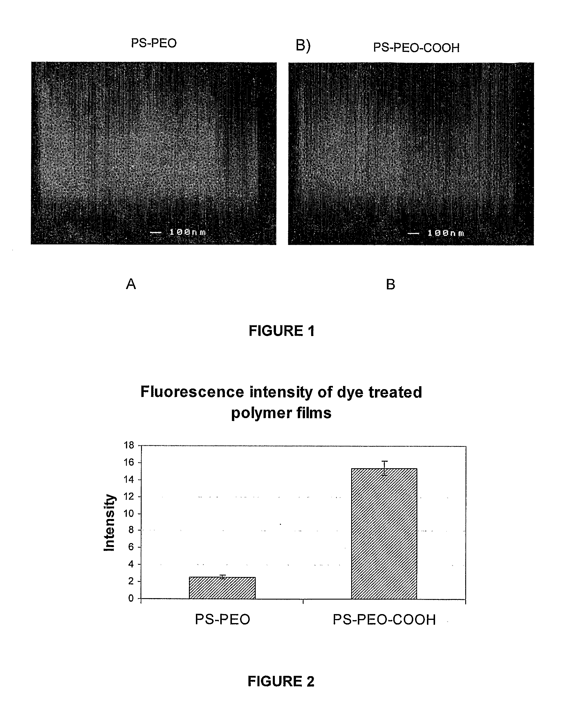
[0143]This example demonstrates the production of an A-B-C block copolymer system where the addition of a terminal C group, carboxylic acid, to an A-B diblock copolymer of PS-PEO, which does not affect the phase behaviour of A-B diblock copolymer system but allows for the attachment of another molecule to the C group (ie, in this example an amine containing fluorescent dye was conjugated to C terminal groups on the generated surface). The use of an amine containing fluorescent dye allows for a simple determination of the effectiveness of the conjugation via fluorescence microscopy and since most biologically relevant molecules contain an amine group binding this example is representative of the final application of this method.

[0144]Polymer Properties

[0145]

Mn (kDa)PolymerABTotalPolydispersity IndexPS——2021.05PS-PEO5111.562.51.05

[0146]Addition of Terminal Carboxylic Acid Group to PEO

[0147]A solution of 40 mg / mL of PS-PEO and 2 mg / ...

example 2

A-B-C Block Copolymer System of PS-PEO-Maleimide Group

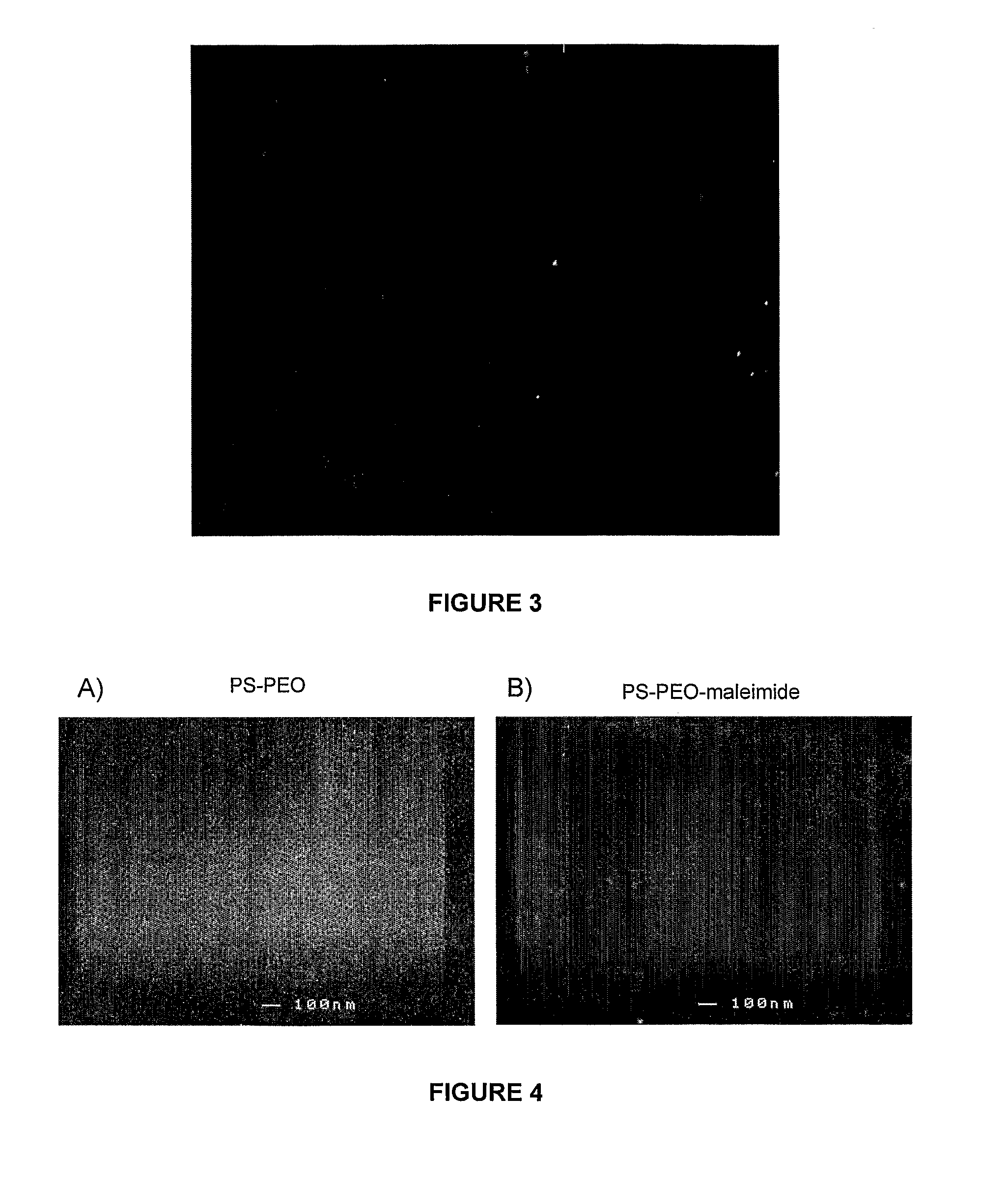
[0154]This example demonstrates the production of an A-B-C block copolymer system where the addition of a terminal C group, maleimide group, to an A-B diblock copolymer of PS-PEO, which does not affect the phase behaviour of A-B diblock copolymer system but allows for the attachment of another molecule. Maleimide groups react specifically with thiol groups forming a stable carbamate bond. Thiol groups are present as side chains on the amino acid cysteine, this maleimide terminal group therefore allows for specific conjugation of biologically relevant molecules.

[0155]Polymer Properties

[0156]

Mn (kDa)PolymerABTotalPolydispersity IndexPS——2021.05PS-PEO5111.562.51.05

[0157]Addition of Terminal Maleimide Group to PEO

[0158]A solution of 50 mg / ml of PS-PEO and 8 mg / ml of N-(p-Maleimidophenyl)isocyanate (PMPI) (Pierce, Rockford, Ill.) in dimethyl formamide (DMF) was stirred for 4 hours at room temperature. The addition of a maleimide group...

example 3

Phase Behaviour of Polymer of Example 2

[0163]In this example we describe the microphase separation of the PS-PEO A-B diblock copolymer and terminally derivatized A-B-C block copolymer system during the 3-dimensional scaffold manufacture process. Microphase separation is shown to occur on scaffolds fabricated via TIPS for both liquid-liquid phase separating systems and solid-liquid phase separating systems.

[0164]Polymer Properties

[0165]

Mn (kDa)PolymerABTotalPolydispersity IndexPS——2021.05PS-PEO5111.562.51.05

[0166]Addition of Terminal Maleimide Group to PEO

[0167]A solution of 50 mg / ml of PS-PEO and 8 mg / ml of N-(p-Maleimidophenyl)isocyanate (PMPI) (Pierce, Rockford, Ill.) in dimethyl formamide (DMF) was stirred for 4 hours at room temperature. The addition of a maleimide group occurs via the reaction of isocyanate with the terminal hydroxyl group of the PEO (Scheme 2 above). The reaction products were then recovered by removal of the solvent in vacuo, re-dissolved in chloroform and pr...


PUM

PropertyMeasurementUnit
thicknessaaaaaaaaaa
domain sizesaaaaaaaaaa
thicknessaaaaaaaaaa

Abstract

A method of producing a structure having a polymer surface with a plurality of surface domains, the surface being formed by the steps of: forming a liquid composition comprising at least one surface polymer, at least one block copolymer and at least one common solvent, the at least one block copolymer having the general formulae A-B-C, wherein A is a polymer which is the same as the surface polymer or fully miscible or partially immiscible with the surface polymer; B is a polymer which is more immiscible in the surface polymer than polymer A; and C is a terminal group; and solidifying the liquid composition to form the structure having the surface with the plurality of surface domains.

Description

[0001]This application is the U.S. national phase of International Application No. PCT / AU2010 / 000405, filed 9 Apr. 2010, which designated the U.S. and claims priority to Australia Application No. 2009901555, filed 9 Apr. 2009, the entire contents of each of which are hereby incorporated by reference.FIELD OF THE INVENTION[0002]The present invention relates generally to polymer structures having functionalised surface characteristics and to a method for preparing the same. The polymer structures are particularly suitable for use in the field of biomaterials where the attachment of desirable molecules to a surface is required, and it will therefore be convenient to describe the invention with an emphasis toward this application. However, it is to be understood that the polymer structures may be used in various other applications.BACKGROUND OF THE INVENTION[0003]The working environment for many polymers requires attachment of desirable molecules to the polymer (then acting as a substra...

Claims


Application Information

Patent Timeline
Patent Type & Authority Patents(United States)
IPC IPC(8): C08L53/00C08G65/333A61L27/48C08G65/332C08L71/02C08L25/06C08L87/00
CPCC08G65/3328C08G65/33337C08G65/33358C08L25/06C08L71/02A61L27/48C08L53/00C08L87/005C08L2205/05Y10T428/24802C08L2666/24C08L2666/06
Inventor GEORGE, PETERCOOPER-WHITE, JUSTIN, JOHNCROLL, TRISTAN
Owner THE UNIV OF QUEENSLAND
Learn More