
Camera and shutter device

a technology of shutter device and camera, which is applied in the direction of shutter, exposure control, instruments, etc., can solve the problems of accidental turning on of the switch, different brightness of the photographic object, and inability to adjust the shutter speed,

Inactive Publication Date: 2003-11-06
FUJIFILM CORP
View PDF1 Cites 0 Cited by
  • Summary
  • Abstract
  • Description
  • Claims
  • Application Information

AI Technical Summary

Benefits of technology

[0008] Another object of the present invention is to provide a camera in which a shutter mechanism can be actuated stably with sufficient delay time, and a shutter device.
[0009] A further object of the present invention is to provide a camera in which assembly of relevant elements can be facilitated even in a structure with a flash unit and an aperture stop changer mechanism, and a shutter device.
[0010] Still another object of the present invention is to provide a camera in which plural units in which relevant elements are combined can ensure suitability to recycling by disassembly and assembly, and a shutter device.

Problems solved by technology

However, brightness of a photographic object may be totally different between various types of scene to be photographed.
However, it is likely in the known camera that the photometric switch in a form of leaf switch is turned on accidentally upon occurrence of external shock or vibration to a camera body.
Thus, it is possible that the shutter mechanism is actuated stably with sufficient delay time, because the friction mechanism frictionally contacts to the delay lever.

Method used


Image

  • Camera and shutter device
  • Camera and shutter device
  • Camera and shutter device

Examples


Embodiment Construction

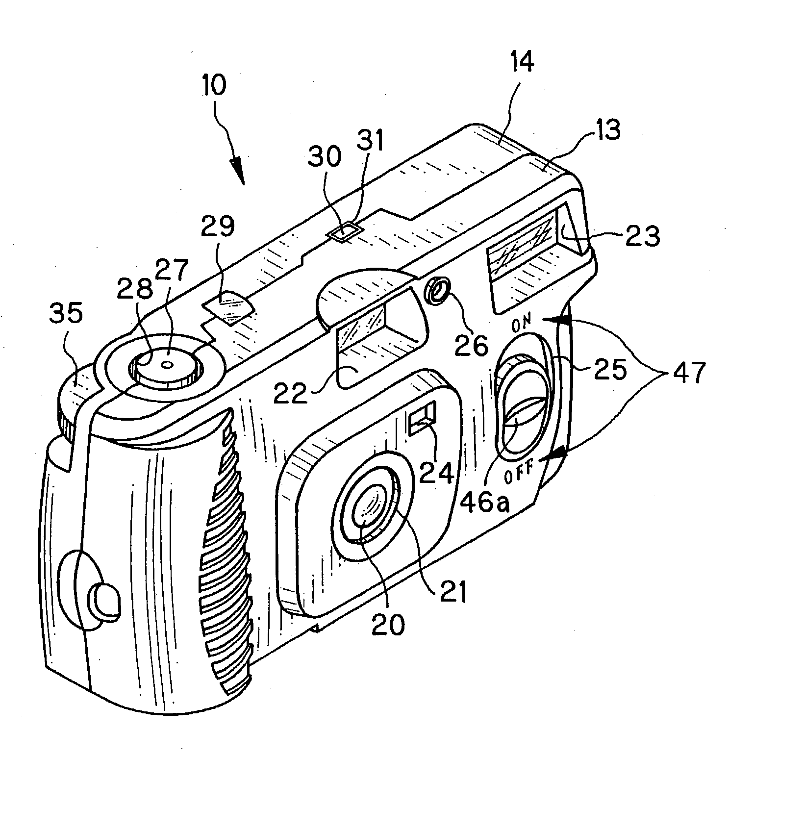
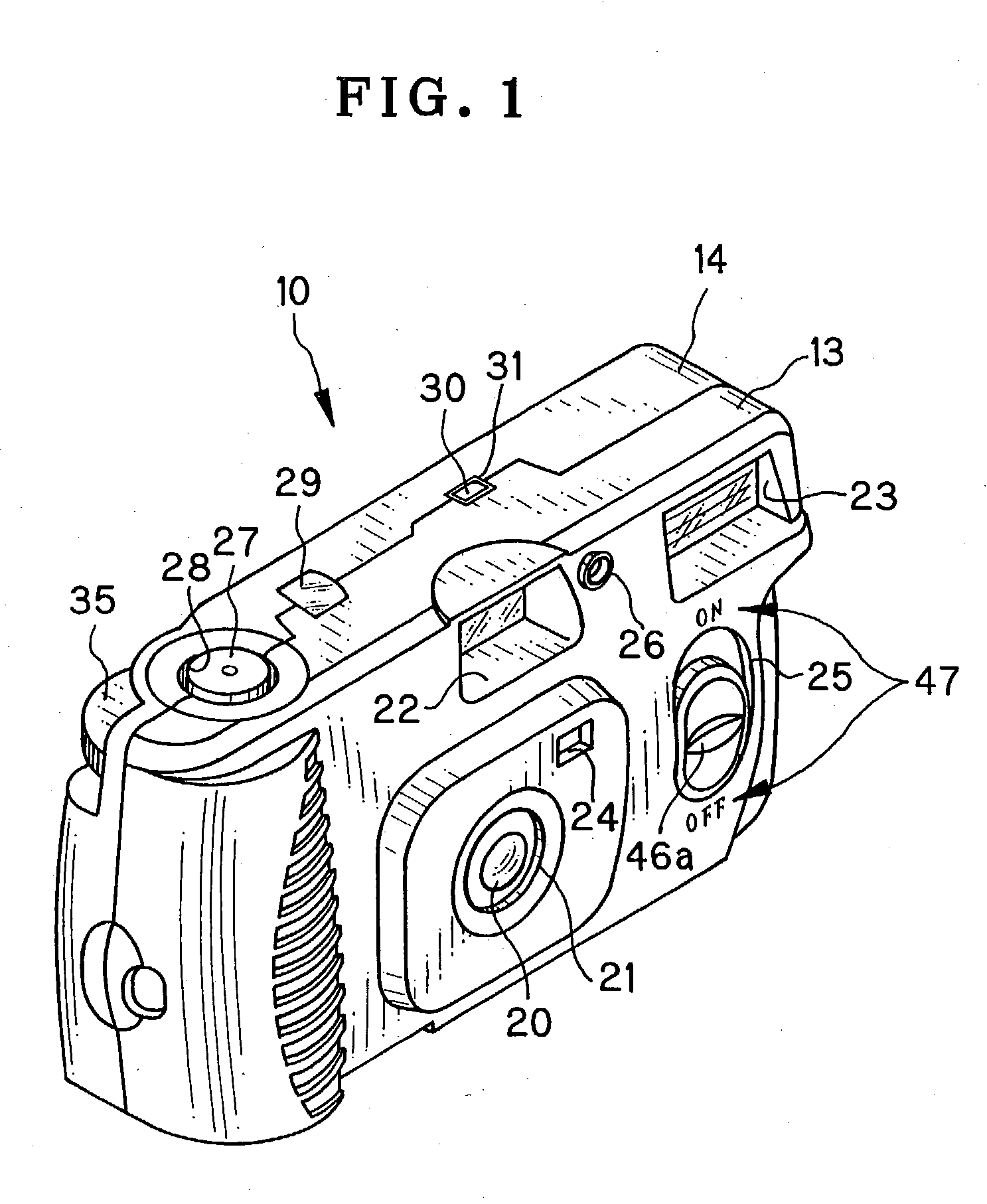
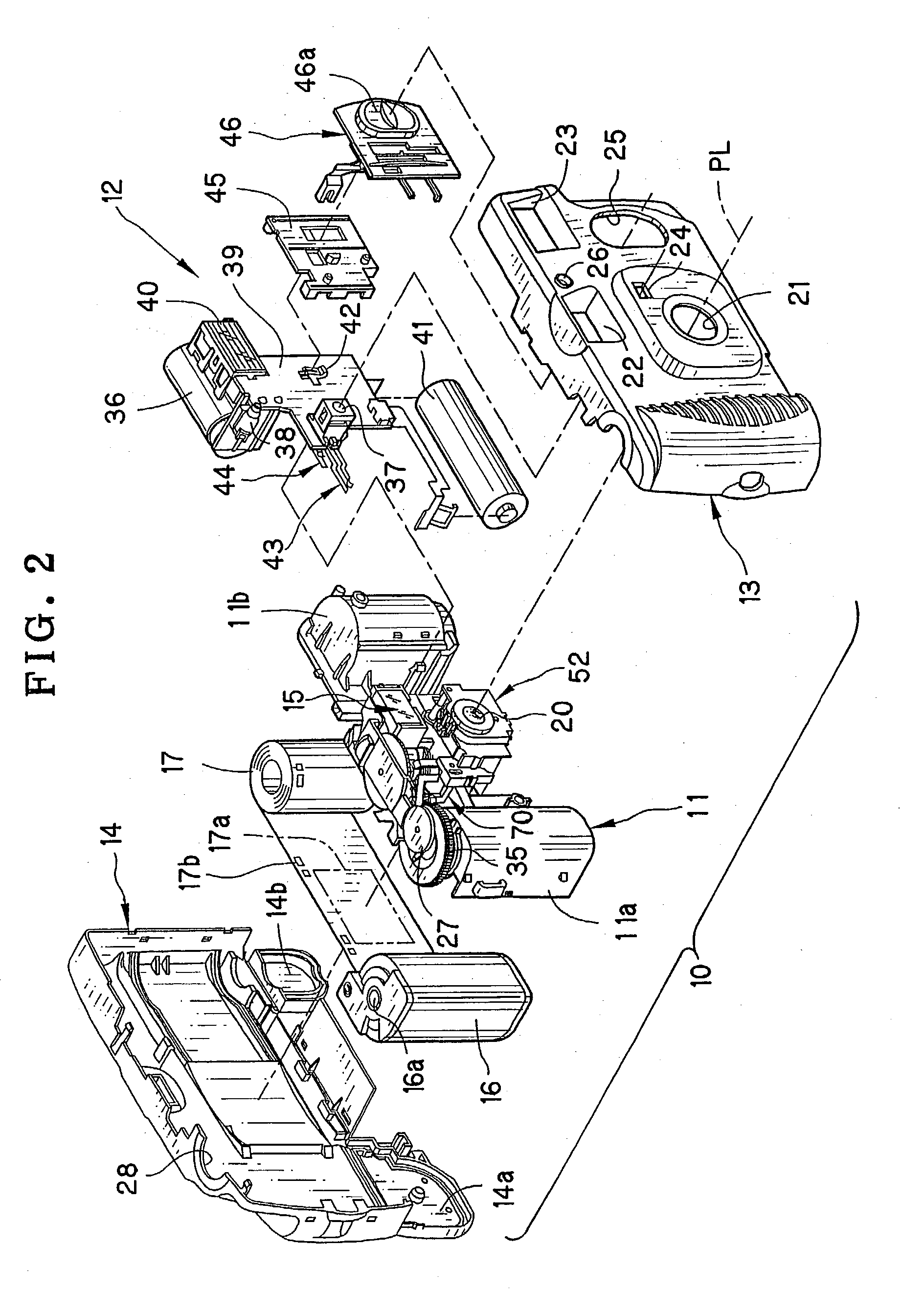
[0053] In FIGS. 1 and 2, a lens-fitted photo film unit 10 is illustrated. A main body 11 in the lens-fitted photo film unit 10 includes various elements for taking exposures, and is provided with an electronic flash unit 12. A front cover 13 and a rear cover 14 are fitted to cover the front and rear of the main body 11 and the flash unit 12. An exposure unit 15 or mechanical unit is disposed in the center of the main body 11. The flash unit 12 is disposed beside the exposure unit 15. In the main body 11 are formed a cassette holder chamber 11a and a photo film holder chamber 11b, between which the exposure unit 15 is disposed. A photo film cassette 16 is inserted in the cassette holder chamber 11a. A photo film 17 is drawn from the photo film cassette 16, wound in a roll form and set in the photo film holder chamber 11b in the course of manufacture.

[0054] In the front cover 13 are formed a front opening 21, a viewfinder objective window 22, a flash emitter window 23, a photometric w...


PUM


Abstract

A camera includes a movable aperture stop plate, which changes over a light path of object light between plural stop states. A depressible shutter release button is provided. A shutter mechanism is released in response to depression of the shutter release button after a charging operation and changing over the movable aperture stop plate, to provide an exposure to the photo film. A photometric circuit including a CdS element measures object brightness adapted for changing over the movable aperture stop plate. A photometric switch includes first and second switch segments, is turned on when pressed, to supply the photometric circuit with power. A blocking pin blocks and turns off the first and second switch segments upon completion of the charging operation of the shutter mechanism, and comes away from the photometric switch when the shutter release button is depressed.

Description

[0001] 1. Field of the Invention[0002] The present invention relates to a camera and shutter device. More particularly, the present invention relates to a camera in which an aperture stop is changed over according to object brightness, and an exposure is taken after the aperture stop is set, and a shutter device.[0003] 2. Description Related to the Prior Art[0004] A lens-fitted photo film unit is known in the field of photograph as a camera of simple type, and pre-loaded with photo film in the course of manufacture. A lens in the lens-fitted photo film unit is a fixed focus type for the purpose of reducing a cost and structure. For the same purpose, a shutter in the lens-fitted photo film unit is a knocking type in which a shutter blade opens and shuts upon knocking operation, and of which a shutter speed is fixed. However, brightness of a photographic object may be totally different between various types of scene to be photographed. The brightness may be very low because of weak il...

Claims


Application Information

Patent Timeline
Patent Type & Authority Applications(United States)
IPC IPC(8): G03B7/00G03B7/08G03B7/085G03B7/095G03B7/16G03B9/04G03B9/10
CPCG03B7/003G03B7/08G03B7/085G03B9/10G03B7/16G03B9/04G03B7/095
Inventor NOGUCHI, OSAMUMIKAMI, YUJI
Owner FUJIFILM CORP
Learn More