
Channelization code sharing between multiple users

a channelization and code technology, applied in the field of data exchange in a communications network, can solve the problem that hspa cannot reduce the resulting latency/delay, and achieve the effect of reducing the amount of memory required and the memory and buffer size of the mobile station

Active Publication Date: 2015-09-29
HMD GLOBAL
View PDF14 Cites 1 Cited by
  • Summary
  • Abstract
  • Description
  • Claims
  • Application Information

AI Technical Summary

Benefits of technology

The patent text explains a method for improving the performance of radio networks and reducing latency in data transmission. By reducing the delay in transmitting data from the base station to the user equipment (UE), the network can provide better performance and higher data rates. Additionally, by using less memory and buffer space in the UE devices, the amount of memory needed can be reduced. Overall, this method improves the efficiency and performance of wireless communication networks.

Problems solved by technology

As the data rates keep increasing in the future, the resulting buffers will grow even more and earlier solutions employed in HSPA will not be able to reduce the resulting latency / delay.

Method used


Image

  • Channelization code sharing between multiple users
  • Channelization code sharing between multiple users
  • Channelization code sharing between multiple users

Examples


first embodiment

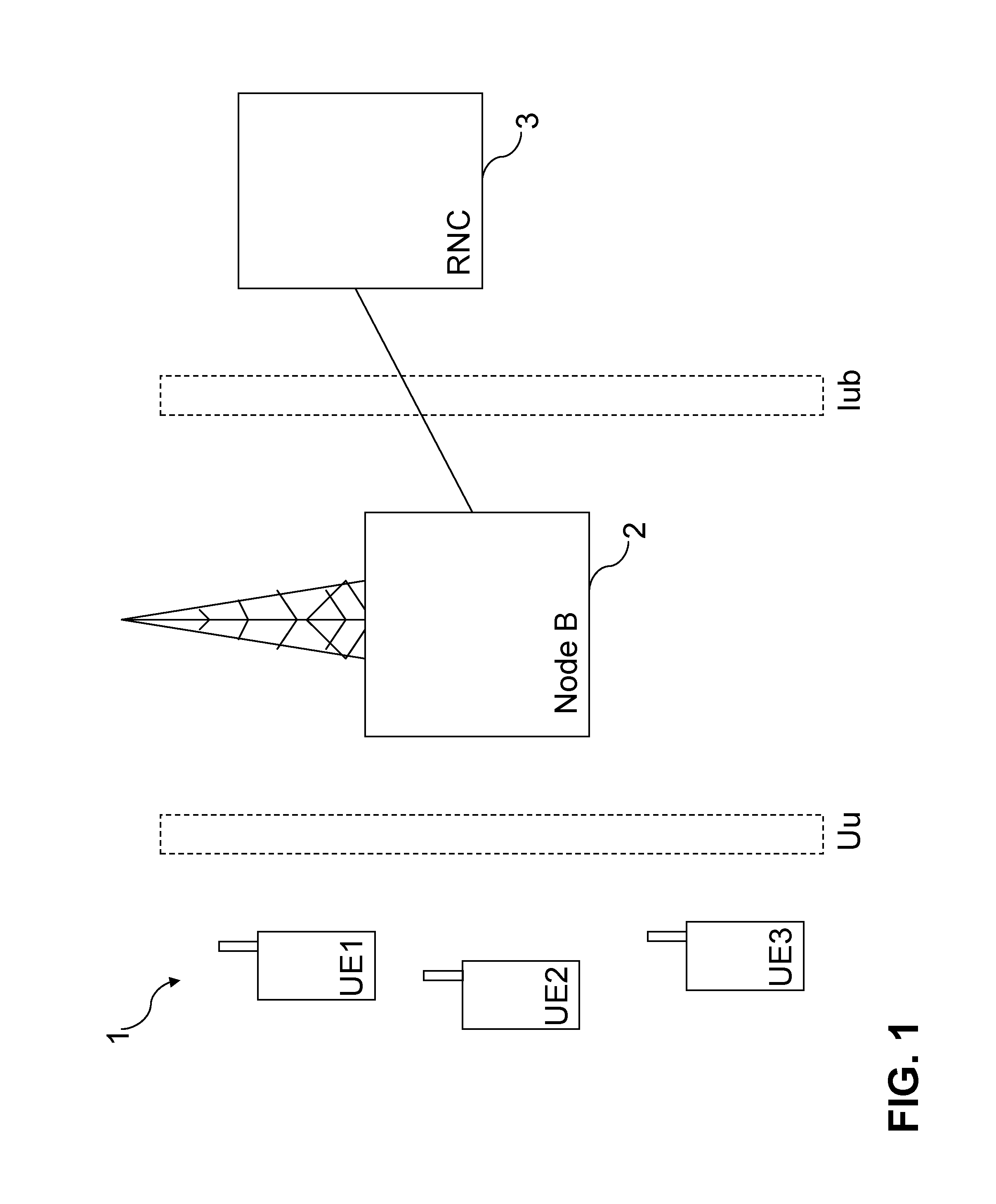
[0040]In the invention, during downlink data transmission in the network, the processor P in the NodeB 2 selects whether to allocate more than one user during 2 ms TTI. In case more than one user is to be allocated, the processor P in the Node B 2 selects the channelization code of the HS-SCCH control channel C1, C2 or C3 to be used for each UE UE1, UE2 and UE3, respectively, using time division multiplexing (TDMA) and code division multiplexing (CDMA) such that the channelization code used for the HS-SCCH control channel C1, C2 or C3 is shared between the UEs UE1, UE2 and UE3 in a TDMA fashion and also in a CDMA fashion over the TTI and corresponds to the part of the 2 ms frame to be allocated to a particular UE UE1, UE2 or UE3 (and to be received by the UE at its receiver R1).

[0041]In other words, the channelization codes C1, C2 or C3 of the control channel are “mapped” to a respective UE UE1, UE2 or UE3, and the channelization codes on the HS-SCCH control channel are time multipl...

second embodiment

[0048]FIGS. 7 and 8 are schematic block diagrams of the channel structure used in the method according to the invention. A flow chart illustrating the method shown in FIGS. 7 and 8 is shown in FIG. 9. The HS-PDSCH carries user data and the HS-SCCH is a fixed data rate control channel carrying channelization code information necessary for HS-PDSCH demodulation by the UE UE1, UE2, UE3. All the UEs UE1, UE2 and UE3 are configured in MIMO mode.

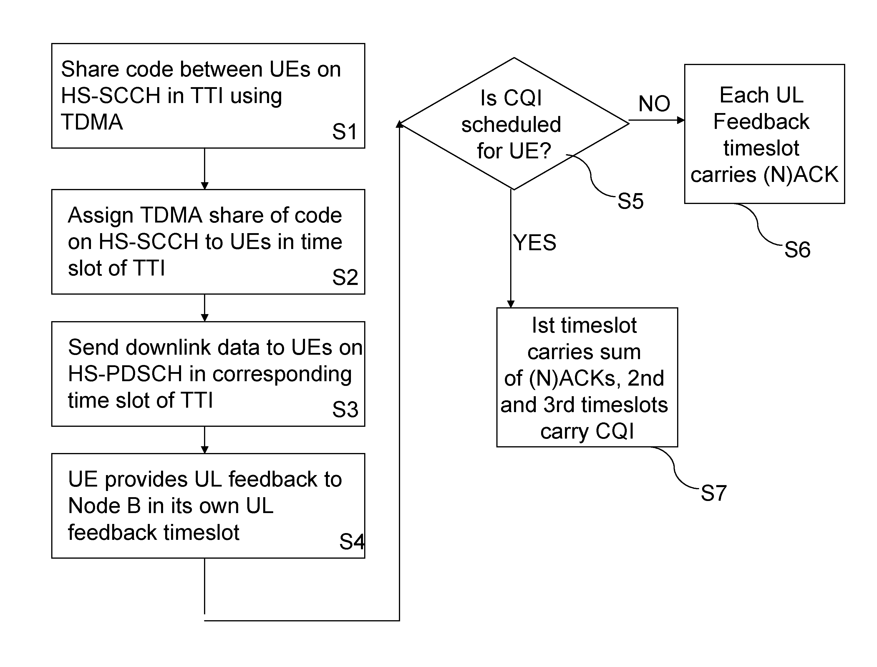
[0049]In the second embodiment of the invention, during downlink data transmission in the network, the processor P in the NodeB 2 selects whether to allocate more than one user during 2 ms TTI. In case more than one user is to be allocated, the processor P in the Node B 2 selects the channelization code of the HS-SCCH control channel C1, C2 or C3 to be used for each UE UE1, UE2 and UE3, respectively, using time division multiplexing (TDMA) (Step S11) such that the channelization code used for the HS-SCCH control channel C1, C2 or C3 corresponds to...


PUM


Abstract

A method of exchanging data in a communications network is provided. A control channel channelization code is assigned for transmitting user specific data channel allocation information to a particular mobile station (MS). The data channel allocation information indicates which part of the transmission time interval (TTI) available for data can be used by that particular MS. The control channel channelization code is shared in a TDMA fashion between the MSs during the TTI in a proportion equal to that in which the data channel channelization code is shared between the MSs such that each MS is allocated a share of the control channel channelization code in that part of the TTI. The control channel channelization code is then transmitted in a part of the TTI corresponding to that in which the data channel channelization code is transmitted for a particular MS.

Description

FIELD OF THE INVENTION[0001]The invention generally relates to a method of exchanging data in a communications network. More particularly, the invention relates to reducing the latency / delay in 3GPP HSPA networks.BACKGROUND OF THE INVENTION[0002]The demand for higher data rates and the growth of mobile broadband services continues to push the need to advance HSPA (high speed packet access) technology.[0003]For example, 3GPP HSDPA (high speed downlink packet access) with Multiple Input Multiple Output (MIMO) transmission has been defined in 3GPP Release 7 to enable a 28 Mbps data rate. The combination of MIMO and 64QAM provides a 42 Mbps in Release 8 and in Release 9, dual cell HSDPA and MIMO and 64 QAM are defined to enable 84 Mbps. Release 10 will be approaching even higher data rates with 168 Mbps being achievable by having four carriers and MIMO. With the increased data rates, the buffer sizes in the devices (user equipment or UEs) also increase when the delay is unchanged.[0004]...

Claims


Application Information

Patent Timeline
Patent Type & Authority Patents(United States)
IPC IPC(8): H04L1/02H04B7/26H04W72/04H04J13/16H04J3/24H04J3/16H04L1/16
CPCH04W72/0406H04B7/2618H04J13/16H04W72/20
Inventor HOLMA, HARRI KALEVITOSKALA, ANTTI ANTON
Owner HMD GLOBAL
Learn More