
Apparatus and method for plasma processing

a plasma processing and apparatus technology, applied in the direction of plasma technique, coating, electric discharge lamps, etc., can solve the problems of plasma and process non-uniformity, rf fluctuations are especially harmful to plasma processing, and plasma chemical processes carried out in inductive plasma are fast and produce low ion damage to semiconductor wafers and devices

Active Publication Date: 2015-09-15
LAM RES CORP
View PDF10 Cites 17 Cited by
  • Summary
  • Abstract
  • Description
  • Claims
  • Application Information

AI Technical Summary

Benefits of technology

The present invention is about an apparatus for plasma processing. It includes a chamber for plasma processing with an external wall, an inductor for providing a radio frequency induction field that is adjacent to the chamber, and a grounded terminal of the inductor located at a central position. The inductor can be capacitively symmetric or geometrically symmetric with respect to the central position. The apparatus can also have multiple inductors, a flat roof with inner and outer ring grooves, and a single RF generator for each inductor. The invention also includes a method for plasma processing using the apparatus. The technical effects of the invention include improved plasma processing efficiency, better uniformity of plasma processing, and reduced damage to the workpiece during processing.

Problems solved by technology

Plasma chemical processes carried out in inductive plasma are fast and produce low ion damages to semiconductor wafers and devices.
The RF fluctuations are especially harmful for plasma processing because of electrical damages to production wafers and generation of parasitic RF capacitive plasmas or RF sheaths in the process chambers.
The parasitic capacitive currents from the inductors are the main cause of plasma and process non-uniformity, several kinds of damages to the process chambers (e.g., arcing) and production wafers, and substantial increase in RF power losses.
It is difficult to build efficient self-resonant inductors in a limited space of compact low-aspect-ratio (more or less flat) high density plasma reactors.

Method used


Image

  • Apparatus and method for plasma processing
  • Apparatus and method for plasma processing
  • Apparatus and method for plasma processing

Examples


first embodiment

(a) First Embodiment

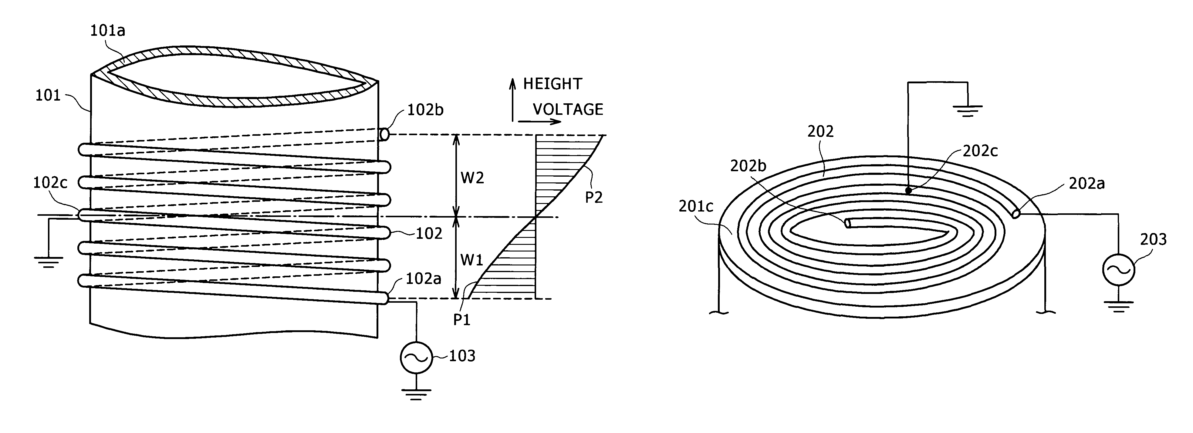
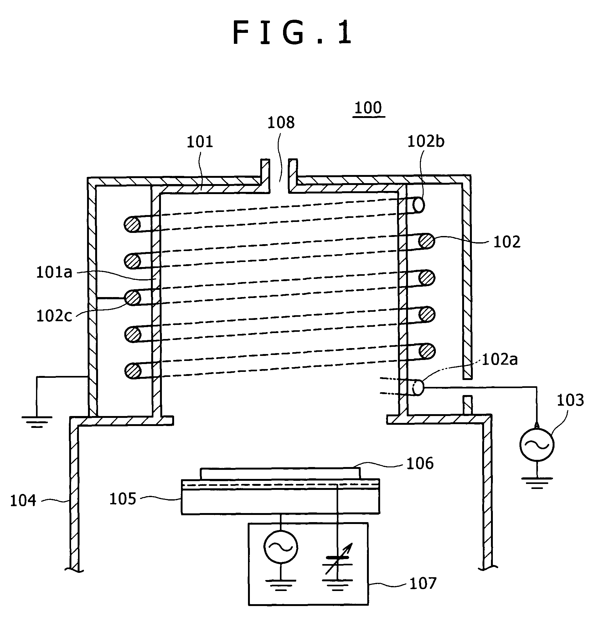
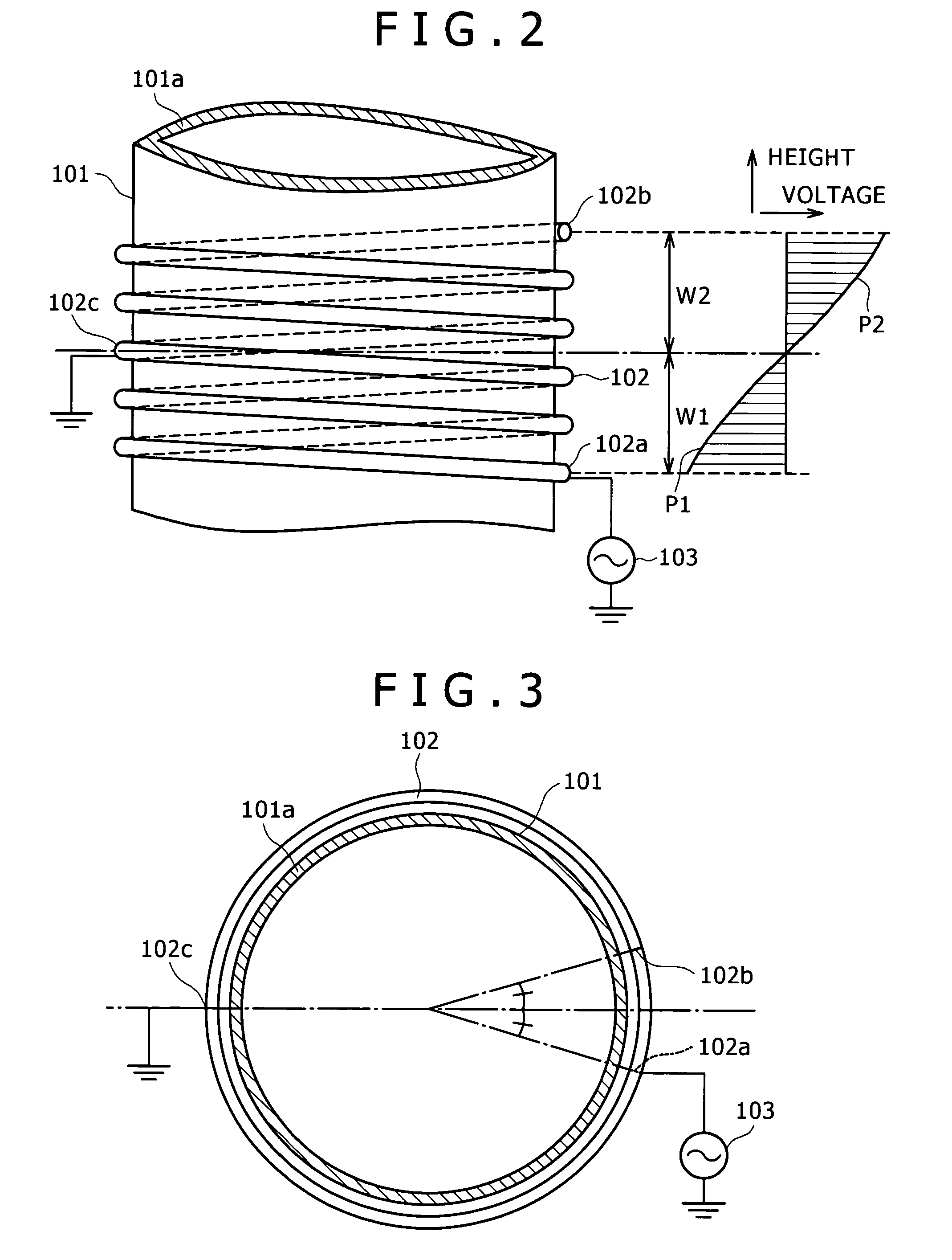
[0037]FIG. 1 is an exemplary illustration of a simplified cross-sectional view of the plasma processing apparatus according to the present invention. The plasma processing apparatus 100 includes an induction chamber 101 that is coupled with a process chamber 104, therefore the process gases can be provided to a workpiece 106 from a gas inlet 108. The process chamber 104 is equipped with a pedestal 105 that is temperature-stabilized (temperature stabilized susceptor or an electrostatic chuck—ESC), and is coupled with a controlled bias RF power supply 107. The controlled bias RF power supply 107 is independently controlled from a RF power supply 103, which provides RF signal frequencies ranging from 800 kHz to 80 MHz to an inductive coil 102. A preferred, non-limiting exemplary RF signal frequencies range from 1 MHz to 60 MHz may be used plasma etching.

[0038]FIG. 2 is an exemplary illustration of a side view of the induction chamber 101 and the induction coil 102 (...


PUM

PropertyMeasurementUnit
RF currentsaaaaaaaaaa
frequenciesaaaaaaaaaa

Abstract

The present invention discloses an apparatus for plasma processing comprising of a chamber for plasma processing with an external wall, and at least one induction coil for providing a radio frequency induction field that is adjacent to the chamber. It further includes an end terminal of the induction coil that is connected to a radio frequency power supply, another end terminal of the induction coil that is open-ended, and a grounded terminal of the induction coil that is located at substantially central position of the induction coil.

Description

BACKGROUND OF THE INVENTION[0001](1) Field of the Invention[0002]The present invention relates to an apparatus and a method for plasma processing.[0003](2) Description of Related Art[0004]Inductively Coupled Plasma (ICP) sources generate inductive plasma through the inductive magnetic field, which in turn produces circular (vortex) electric field accelerating electrons to ionize process gases and sustain plasma discharge. The inductive plasma is usually characterized with medium to high plasma (electron and / or ion) density and low level of Radio Frequency (RF) potential fluctuations. Plasma chemical processes carried out in inductive plasma are fast and produce low ion damages to semiconductor wafers and devices. Well-designed inductive discharges operate in substantially wider range of discharge conditions (e.g., gas pressure and power) in comparison with Capacitively Coupled Plasma (CCP) sources.[0005]It is known in the art that high power (up to several kilowatts) inductors carry...

Claims


Application Information

Patent Timeline
Patent Type & Authority Patents(United States)
IPC IPC(8): H01L21/306C23C16/00H01J37/32H05H1/46
CPCH05H1/46H01J37/321H01J37/32174H01J37/3244
Inventor VINOGRADOV, GEORGY K.MENAGARISHVILI, VLADIMIR M.
Owner LAM RES CORP
Learn More