
Substrate supporting table, method for producing same, and processing system

a supporting table and substrate technology, applied in non-linear optics, instruments, mechanical equipment, etc., can solve the problems of difficult uniform preparation of protruding portions, easy accumulation of dust produced by plasma processing, and high cost and time, so as to reduce the bad influence of deposits, avoid processing irregularities, and prevent circuit patterns

Inactive Publication Date: 2005-06-09
USHIODA JOICHI +3
View PDF14 Cites 354 Cited by
  • Summary
  • Abstract
  • Description
  • Claims
  • Application Information

AI Technical Summary

Benefits of technology

[0013] It is therefore an object of the present invention to provide a substrate supporting table capable of eliminating the above described problems while preventing the disadvantages in that processing irregularities, such as etching irregularity, are caused by the accumulation of the deposits on a substrate supporting table and that a substrate is stuck onto the substrate supporting table, a method for producing the supporting table, and a processing system using the same supporting table.
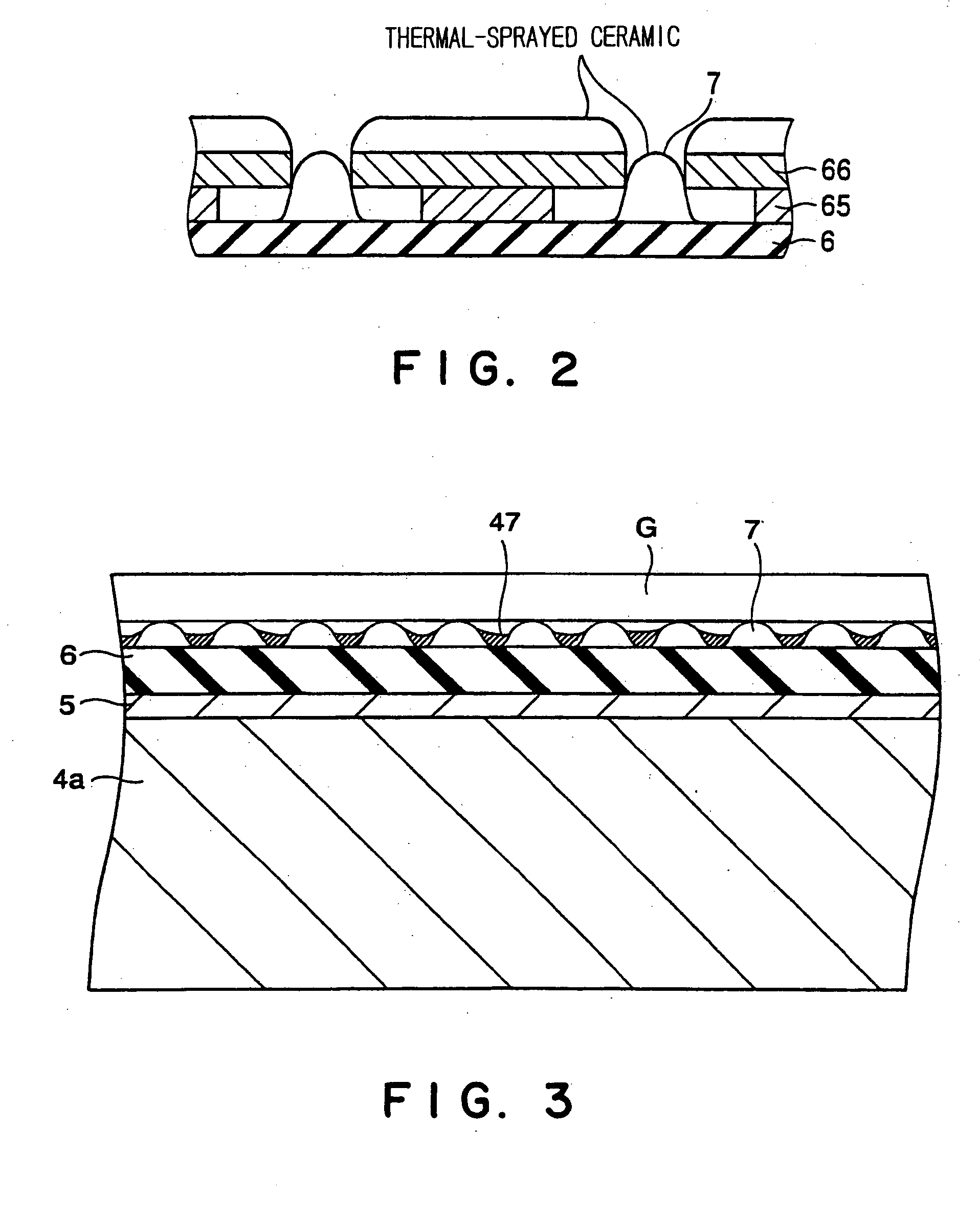
[0020] In the above cases, the protrusions are formed on the dielectric film by thermal-spraying the ceramic, so that the protrusions of the ceramic can be easily and uniformly distributed. These protrusions serve as spacers, so that it is difficult for deposits to contact a substrate to be processed even if the deposits accumulate on the substrate supporting table. Therefore, it is possible to prevent the disadvantages in that portions contacting the substrate supporting table via the deposits are formed in the bottom surface of the substrate to cause etching irregularity and that the substrate is stuck onto the substrate supporting table. It is easy to produce such a substrate supporting table.
[0024] According to these processing systems, it is possible to prevent a circuit pattern formed on the substrate from overlapping with the arrangement pattern of the protrusions, so that it is possible to avoid processing irregularities, such as etching irregularity.
[0025] In any one of the above described constructions, the protrusions preferably point-contact the substrate on the top faces thereof. Thus, it is possible to decrease the bad influence of the deposits. The top faces of the protrusions preferably consist of curved surfaces. Thus, angular portions (sharp-pointed portions) do not exist on the protrusions, so that the protrusions are not scraped off to cause particles.

Problems solved by technology

It is technically difficult to uniformly prepare such protruding portions by the machining of a metal, and it takes costs and a lot of time to do so.
However, in these examples, there is a disadvantage in that dust produced by the plasma processing is easily deposited since the top faces of the protrusions are flat.

Method used


Image

  • Substrate supporting table, method for producing same, and processing system
  • Substrate supporting table, method for producing same, and processing system
  • Substrate supporting table, method for producing same, and processing system

Examples


Embodiment Construction

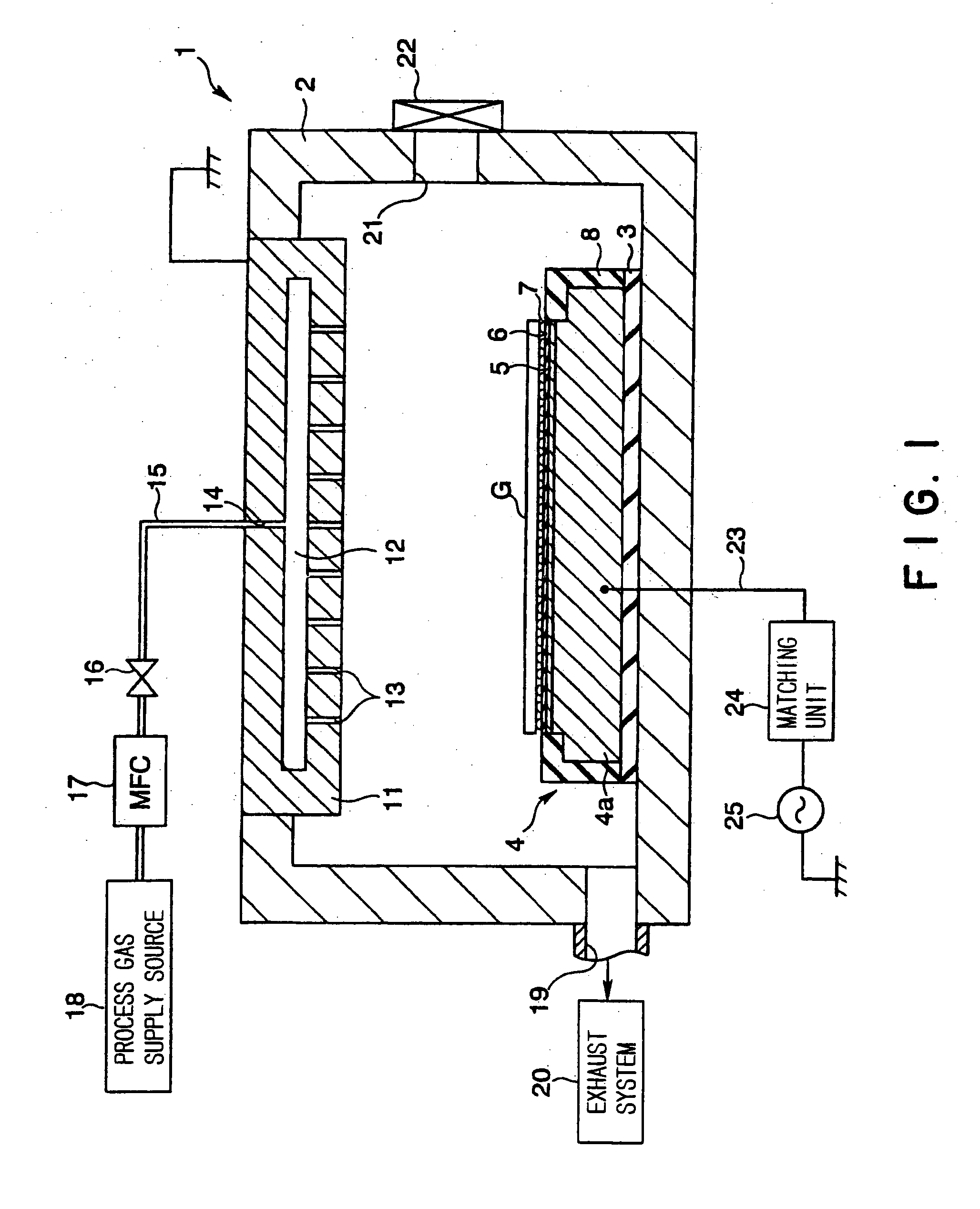
[0036] Referring now to the accompanying drawings, the preferred embodiments of the present invention will be described below.

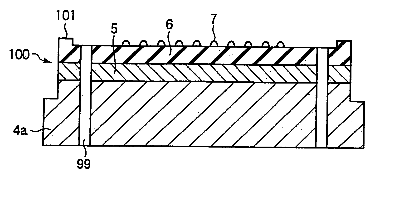
[0037]FIG. 1 is a sectional view showing a preferred embodiment of a plasma etching system in which a susceptor serving as a substrate supporting table according to the present invention is provided. As shown in FIGS. 1 and 3, a susceptor 4 has a base 4a, a dielectric film 6 provided on the base 4a, and a plurality of protrusions 7 formed on the dielectric film 6.

[0038] The protrusions 7 are uniformly distributed in a substrate-supporting region on the dielectric film 6, and a substrate G is supported on the protrusions 7. The protrusions 7 serve as spacers for isolating the susceptor 4 from the substrate G. Thus, it is possible to prevent the substrate G from being adversely influenced by the deposits adhering to the susceptor 4.

[0039] Each of the protrusions 7 preferably has a height of from 50 to 100 μm inclusive. It is possible to sufficiently prevent ...


PUM

PropertyMeasurementUnit
Dielectric polarization enthalpyaaaaaaaaaa
Plasma poweraaaaaaaaaa

Abstract

A plasma processing system has a susceptor, provided in a processing vessel, for supporting thereon a substrate. A process gas is supplied into the processing vessel to produce the plasma of the process gas. The susceptor has a dielectric film formed on a base, and a plurality of protrusions formed on the film. The protrusions of the susceptor are formed by thermal-spraying a ceramic onto the dielectric film via an aperture plate having a plurality of circular apertures.

Description

BACKGROUND OF THE INVENTION [0001] 1. Technical Field [0002] The present invention relates generally to a substrate supporting table for supporting thereon a substrate, such as a glass substrate for a liquid crystal display (LCD), a method for producing the same, and a processing system for carrying out a process, such as dry etching with respect to the substrate by using the substrate supporting table. [0003] 2. Background Art [0004] For example, in LCD manufacturing processes, plasma processing, such as dry etching, sputtering and CVD (Chemical Vapor Deposition), is widely used for processing an LCD substrate of a glass as a substrate to be processed. [0005] In such plasma processing, for example, a pair of parallel plate electrodes (top and bottom electrodes) are arranged in a processing vessel, and a substrate to be processed is supported on a susceptor (supporting table) serving as the bottom electrode. Then, a process gas is fed into the processing vessel, and high-frequency w...

Claims


Application Information

Patent Timeline
IPC IPC(8): C23C16/458H01L21/683G02F1/13H01L21/3065
CPCC23C16/4581Y10T279/23H01J2237/022H01J37/32082G02F1/13
Inventor USHIODA, JOICHISATO, KOICHISATOYOSHI, TSUTOMUITO, HIROMICHI
Owner USHIODA JOICHI
Learn More