Welded construction and resistance welding method

a technology of resistance welding and welded construction, which is applied in the direction of manufacturing tools, conductors, cell components, etc., can solve the problems of damage to the welding electrode, undesirable small area where electrical current can pass,

Inactive Publication Date: 2015-08-04
HITACHI AUTOMOTIVE SYST LTD
View PDF14 Cites 2 Cited by
  • Summary
  • Abstract
  • Description
  • Claims
  • Application Information

AI Technical Summary

Benefits of technology

[0011]Since this type of curving occurs, on the outer surface of this metallic member on its side opposite to its portion that contacts the projecting portion, the end surface of the corresponding welding electrode only contacts the center region where no curving takes place, in other words only contacts a region of small area that corresponds to the projecting portion. In other words, the area where electrical current can pass becomes undesirably small. Due to this, the density of the electrical current that flows into the metallic member becomes high and the amount of heat that is locally generated in this region becomes great, and the welded portion may thereby be damaged so that it may become impossible to ensure an adequate connection force, or the molten portion of the metallic member may adhere to the welding electrode and may damage the welding electrode.

Problems solved by technology

In other words, the area where electrical current can pass becomes undesirably small.
Due to this, the density of the electrical current that flows into the metallic member becomes high and the amount of heat that is locally generated in this region becomes great, and the welded portion may thereby be damaged so that it may become impossible to ensure an adequate connection force, or the molten portion of the metallic member may adhere to the welding electrode and may damage the welding electrode.

Method used


Image

  • Welded construction and resistance welding method
  • Welded construction and resistance welding method
  • Welded construction and resistance welding method

Examples


embodiment 1

[0057]Overall Structure of a Secondary Cell

[0058]In the following, the welded construction and the welding method of the present invention will be explained with reference to the drawings.

[0059]First a cylindrical secondary cell to which an embodiment of the welded construction of the present invention is applied will be explained.

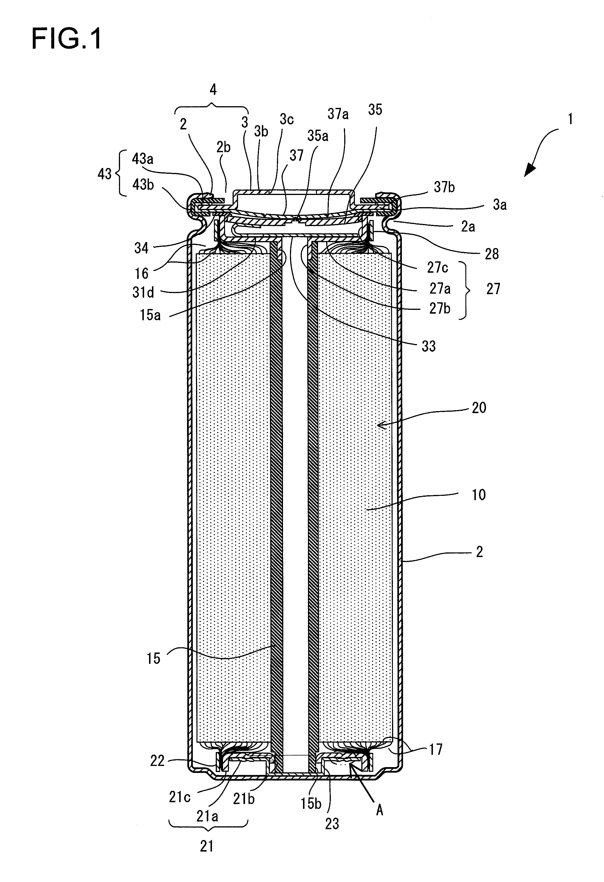
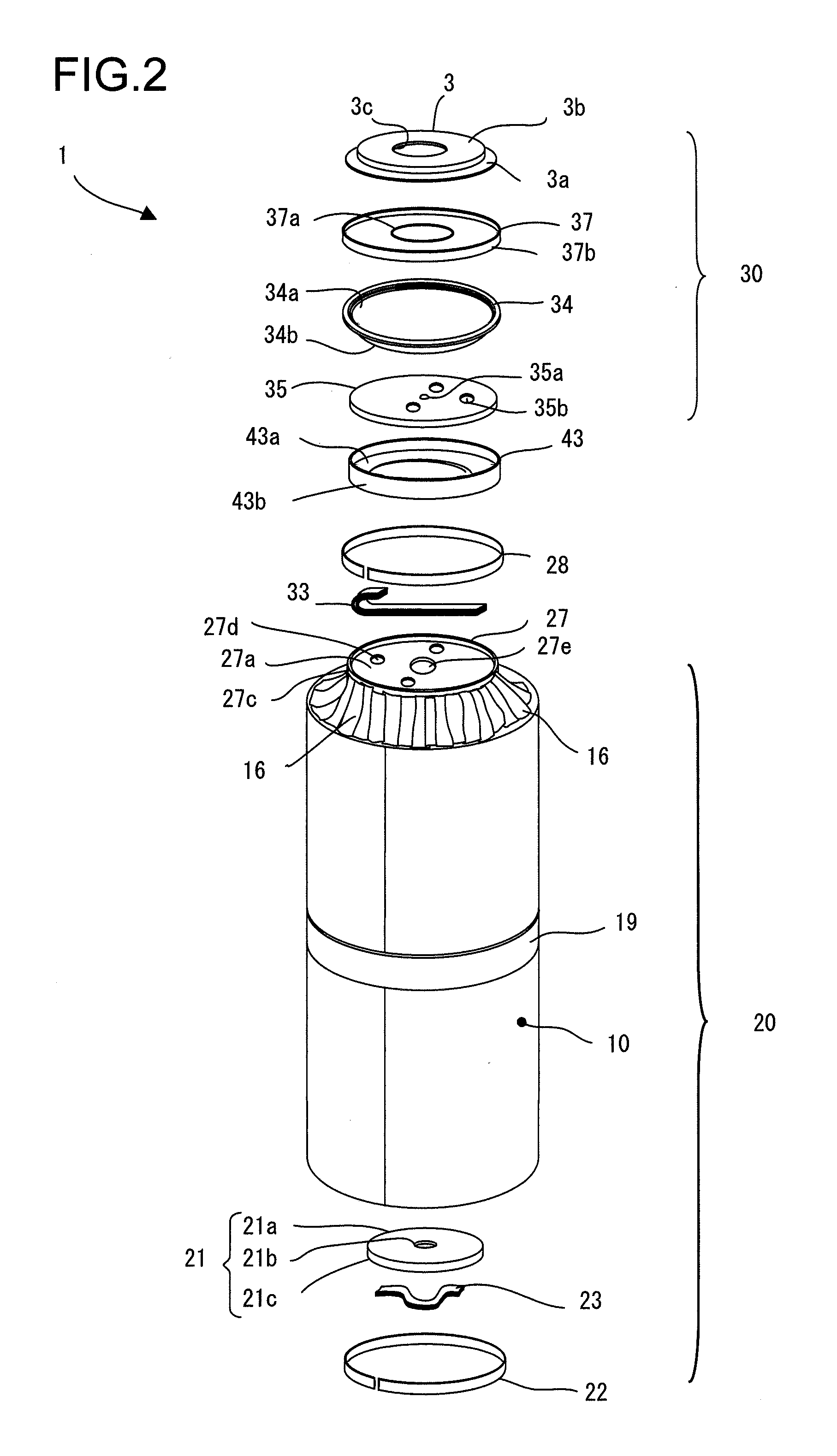
[0060]FIG. 1 is a sectional view of a cylindrical secondary lithium ion cell that is an embodiment of the present invention, and FIG. 2 is an exploded perspective view of the cylindrical secondary cell shown in FIG. 1.

[0061]The cylindrical secondary cell 1, for example, may be shaped as a cylinder that has an external shape of diameter 40 mm and a height of 100 mm. This cylindrical secondary cell 1 has a cell container that is sealed from the exterior, and that is constructed by performing a swaging process so as to clamp a hat shaped cell lid 3 onto the top of a cylindrical cell casing 2 having a bottom, with the interposition of a sealing member 43 (norm...

embodiment # 2

Embodiment #2

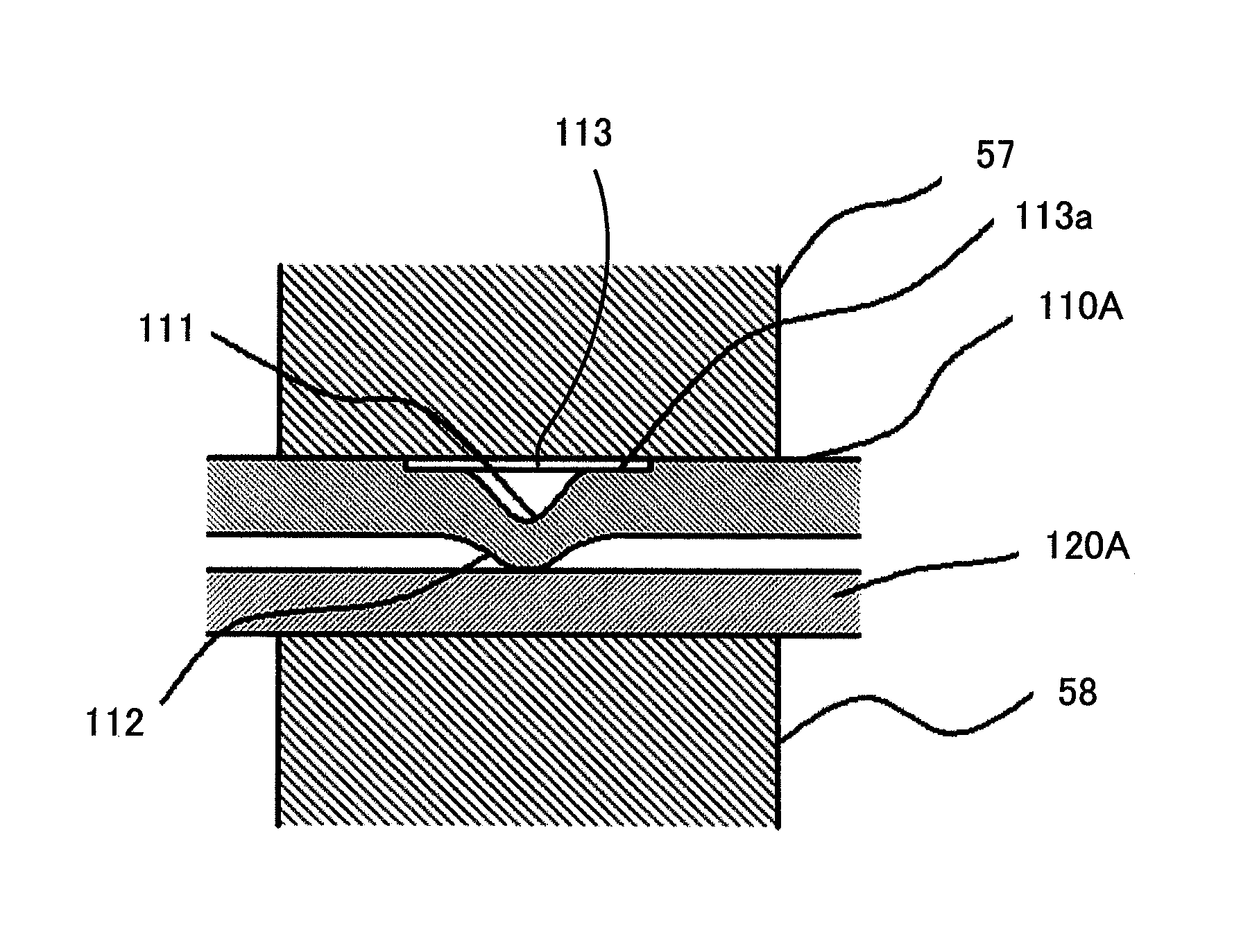
[0136]FIG. 16 shows a second embodiment of the present invention. This figure is an enlarged sectional view for explanation of this construction to be welded, directly before flowing of the electrical current for welding. A depressed portion 111 is formed at the upper portion of the one metallic member 110A shown in FIG. 16, and a recessed portion 113 having a greater width (i.e. diameter) than this depressed portion 111 is formed over the depressed portion 111. Moreover, the other metallic member 120A is a plate shaped member that is all of uniform thickness, and no recessed portion is formed thereupon.

[0137]The bottom surface 113a of the recessed portion 113 formed in the one metallic member 110A does not contact against the lower surface of the movable electrode 57, even during the welding process. Moreover, since the stress concentration acting on the projecting portion 112 of the one metallic member 110A is dispersed, deformation due to bending of the metallic memb...

embodiment # 3

Embodiment #3

[0142]FIG. 18 shows a third embodiment of the present invention. This figure is an enlarged sectional view for explanation of the construction to be welded, directly before flowing of the electrical current for welding. The feature by which this third embodiment shown in FIG. 18 differs from the second embodiment shown in FIG. 16 is that the other metallic member 120 has a concaved portion 121, just like the first embodiment shown in FIG. 5. In other words, in this third embodiment, a recessed portion 113 that does not contact the movable electrode 57 is formed upon the one metallic member 110A, while also the concaved portion 121 that does not contact the fixed electrode 58 is formed upon the other metallic member 120. Since, due to this, the contact area between the fixed electrode 58 and the metallic member 120 is increased, the deformation amounts of the one metallic member and the other metallic member, and the electrical current density is reduced, thus it is poss...


PUM

PropertyMeasurementUnit
widthaaaaaaaaaa
widthaaaaaaaaaa
widthaaaaaaaaaa

Abstract

A welded construction according to the present invention has a first metallic member, on one surface of which a projecting portion is formed and on the other surface of which a depressed portion corresponding to the projecting portion is formed, and a second metallic member are welded together at a welded portion which includes a summit portion of the projecting portion; wherein, on at least one of the first metallic member and the second metallic member, on its opposite surface to its surface that faces the other one of the metallic members, a recessed portion is formed that is recessed from its peripheral region towards a region which corresponds to the welded portion.

Description

[0001]The disclosure of the following priority application is hereby incorporated herein by reference: Japanese Patent Application No. 2010-280493, filed Dec. 16, 2010.BACKGROUND OF THE INVENTION[0002]1. Field of the Invention[0003]The present invention relates to a welded construction and to a method of resistance welding.[0004]2. Description of the Related Art[0005]Resistance welding is per se known as a method of locally welding together two metallic members. Resistance welding is a method of welding by flowing an electrical current through portions where the members are to be welded together and thus generating Joule heat, while at the same time pressing the members together.[0006]In order to locally concentrate the electrical current that flows in the members to the portions to be welded, the contact area is made to be small for achieving higher electrical current density. Due to this, a portion projecting point-wise or line-wise is normally provided on one of the metallic memb...

Claims


Application Information

Patent Timeline
Patent Type & Authority Patents(United States)
IPC IPC(8): B23K11/14B23K11/20
CPCB23K11/14B23K11/20Y10T428/12389B23K2101/38B23K2103/18
Inventor ONOSE, SHINKAWAHARA, KEIJIFUJIMOTO, HIROSHIHASEGAWA, KENTA
Owner HITACHI AUTOMOTIVE SYST LTD
Why Eureka
Try Eureka