High-pressure pump

Active Publication Date: 2013-10-10
TOYOTA JIDOSHA KK
View PDF6 Cites 7 Cited by
  • Summary
  • Abstract
  • Description
  • Claims
  • Application Information

AI Technical Summary

Benefits of technology

The invention is a high-pressure pump that can prevent fuel temperature rise and reduce its impact on controlling the discharge amount. This is achieved by a heat insulating member provided on the spring seat, which curbs heat exchange between the spring seat and the fuel flowing through the space, reducing the amount of heat fuel receives from the spring seat. This reduces the likelihood of vapor production and avoids the influence of temperature rise on the control of discharge amount. The heat insulating member can be formed of low-cost and highly-resistant materials, such as PTFE.

Problems solved by technology

Due to the temperature rise of the fuel, vapor may be produced in the high-pressure pump, and may affect control of the discharge amount of the high-pressure pump.

Method used


Image

  • High-pressure pump
  • High-pressure pump
  • High-pressure pump

Examples


Embodiment Construction

[0021]One embodiment of the invention will be described with reference to the accompanying drawings. In the following embodiment, the invention is applied to a high-pressure pump for use in a vehicle.

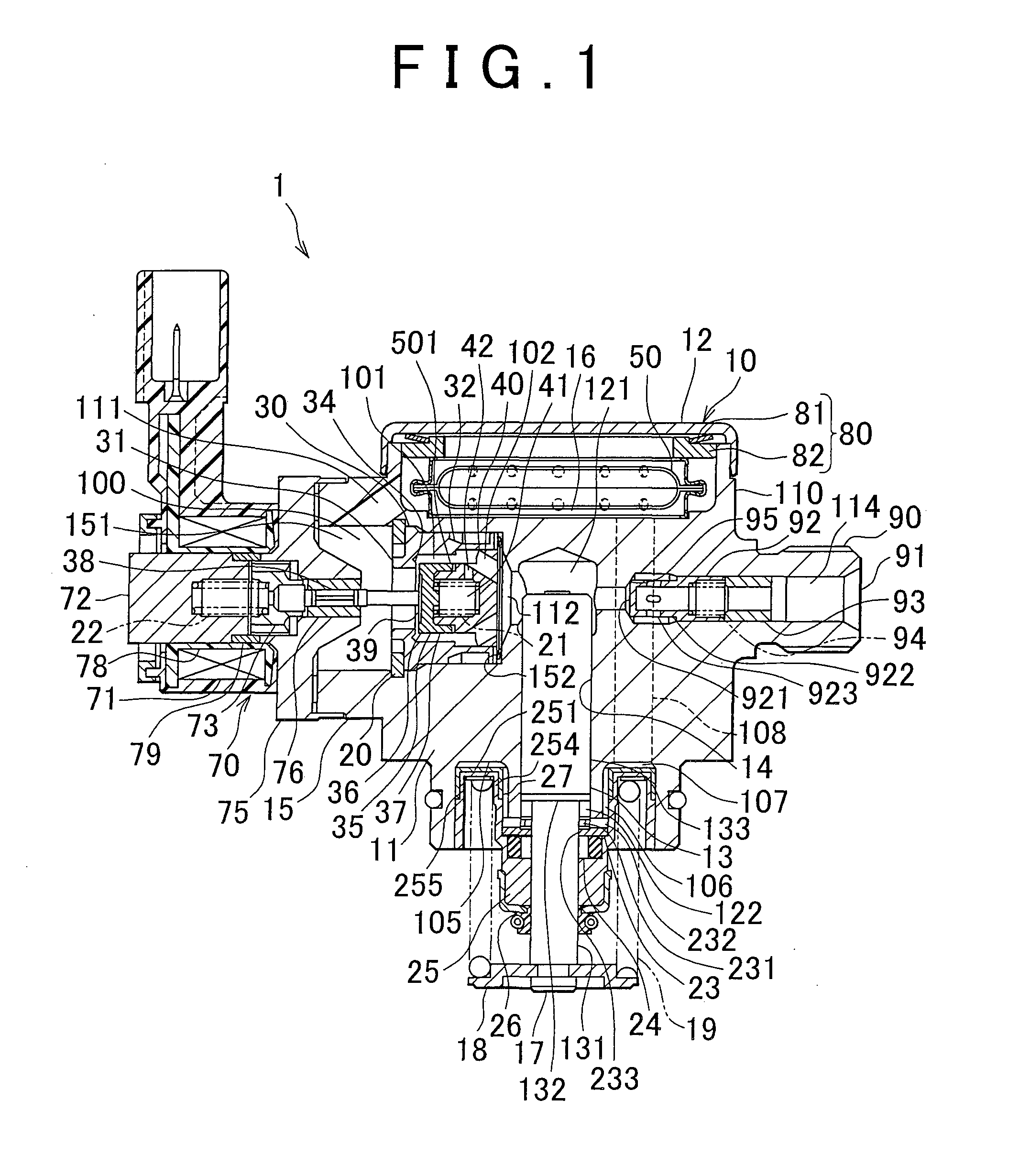
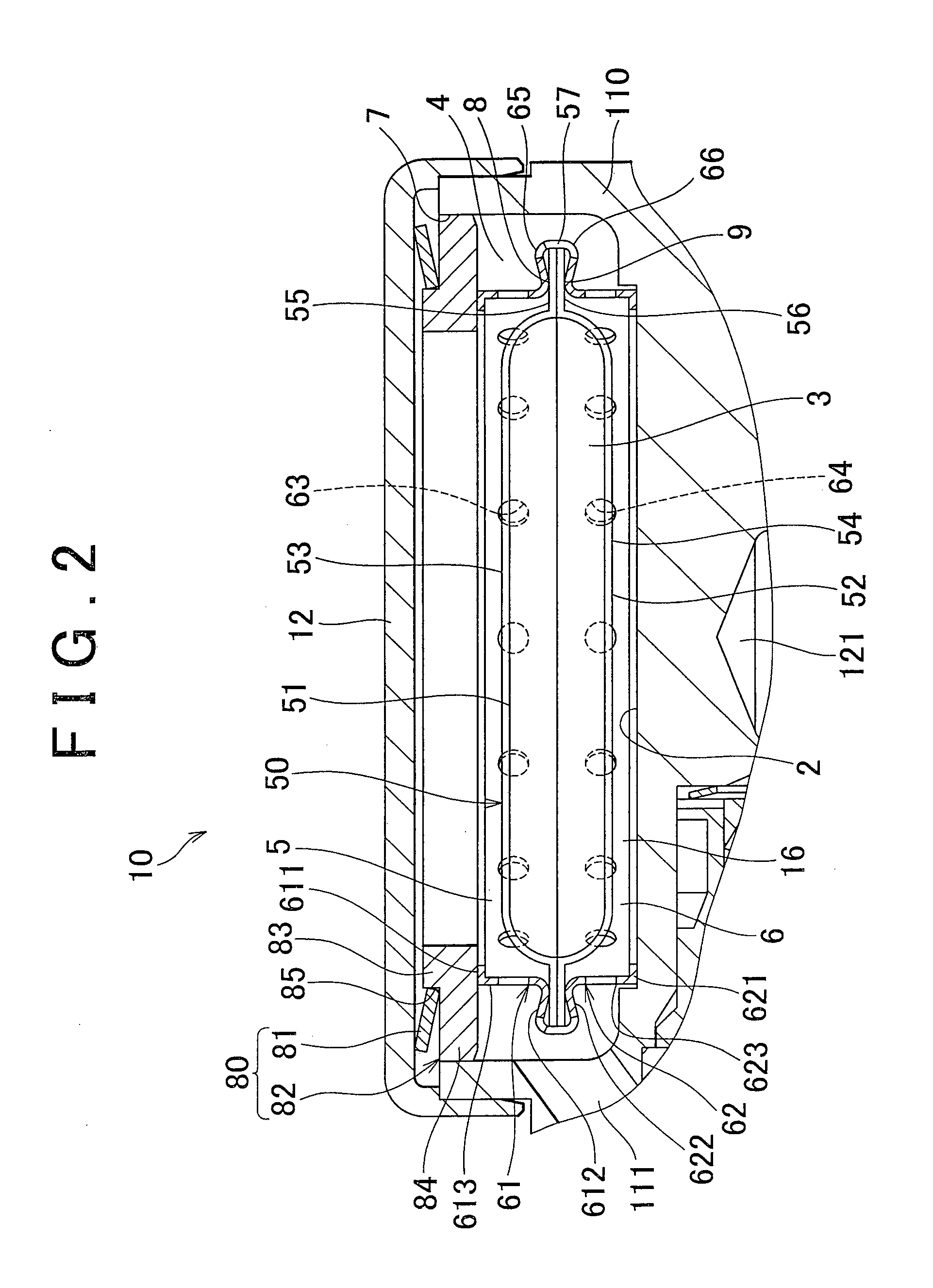
[0022]The high-pressure pump 1 illustrated in FIG. 1 is a fuel pump that supplies fuel to injectors of an engine, such as a diesel engine or a gasoline engine, and is attached to a head cover of the engine, for example. The high-pressure pump 1 includes a housing 11, a plunger 13, a valve body 30, an electromagnetic drive unit 70, a damper device 10, a lid member 12, and so forth.

[0023]The housing 11 is formed of, for example, martensite stainless steel. A cylinder 14 is formed in the housing 11. The plunger 13 is supported in the cylinder 14 such that the plunger 13 can reciprocate in the axial direction. Also, a guide passage 111, an intake passage 112, a pressurizing chamber 121, a discharge passage 114, etc. are formed in the housing 11.

[0024]The housing 11 has a cylindrical portion...


PUM


Abstract

A high-pressure pump includes a plunger capable of reciprocating, and a housing having a pressurizing chamber in which fuel is pressurized by the plunger, and a fuel chamber through which the fuel flows toward and from the pressurizing chamber. The pump includes a spring that biases the plunger so as to increase the volume of the pressurizing chamber, and a spring seat that is fixed to the housing and is in contact with one end of the spring. A first space that communicates with the fuel chamber via a fuel passage is provided between the bottom of the spring seat and the housing, and a top face of the bottom exposed to the first space is covered with a heating insulating member.

Description

BACKGROUND OF THE INVENTION[0001]1. Field of the Invention[0002]The invention relates to a high-pressure pump.[0003]2. Description of Related Art[0004]A high-pressure pump used for supplying fuel to injectors of an internal combustion engine, such as a diesel engine or a gasoline engine, includes a plunger capable of reciprocating in a cylinder, and a housing having a pressurizing chamber in which the fuel is pressurized by the plunger, and a fuel chamber through which the fuel flows toward and from the pressurizing chamber. A known example of the high-pressure pump (as disclosed in, for example, Japanese Patent Application Publication No. 2010-185410 (JP-A-2010-185410)) includes a damper device for dampening pressure pulsation of the fuel which occurs due to reciprocating movement of the plunger.[0005]The high-pressure pump as described in JP-A-2010-185410 includes a spring that biases the plunger in such a direction as to increase the volume of the pressurizing chamber, and a spri...

Claims


Application Information

Patent Timeline
IPC IPC(8): F04B7/02
CPCF02M53/00F02M55/04F04B7/02F02M2200/9015F02M59/44
Inventor AKITA, TATSUHIKOSAITO, KENICHI
Owner TOYOTA JIDOSHA KK
Why Eureka
Try Eureka