
Flow cytometer apparatus for three dimensional difraction imaging and related methods

a flow cytometer and apparatus technology, applied in the field of flow cytometers, can solve the problems of difficult, laborious, complex analysis of existing pattern recognition algorithms, and confocal imaging techniques that are generally not compatible with imaging flow cytometers,

Active Publication Date: 2015-04-21
HU XIN HUA
View PDF20 Cites 20 Cited by
  • Summary
  • Abstract
  • Description
  • Claims
  • Application Information

AI Technical Summary

Benefits of technology

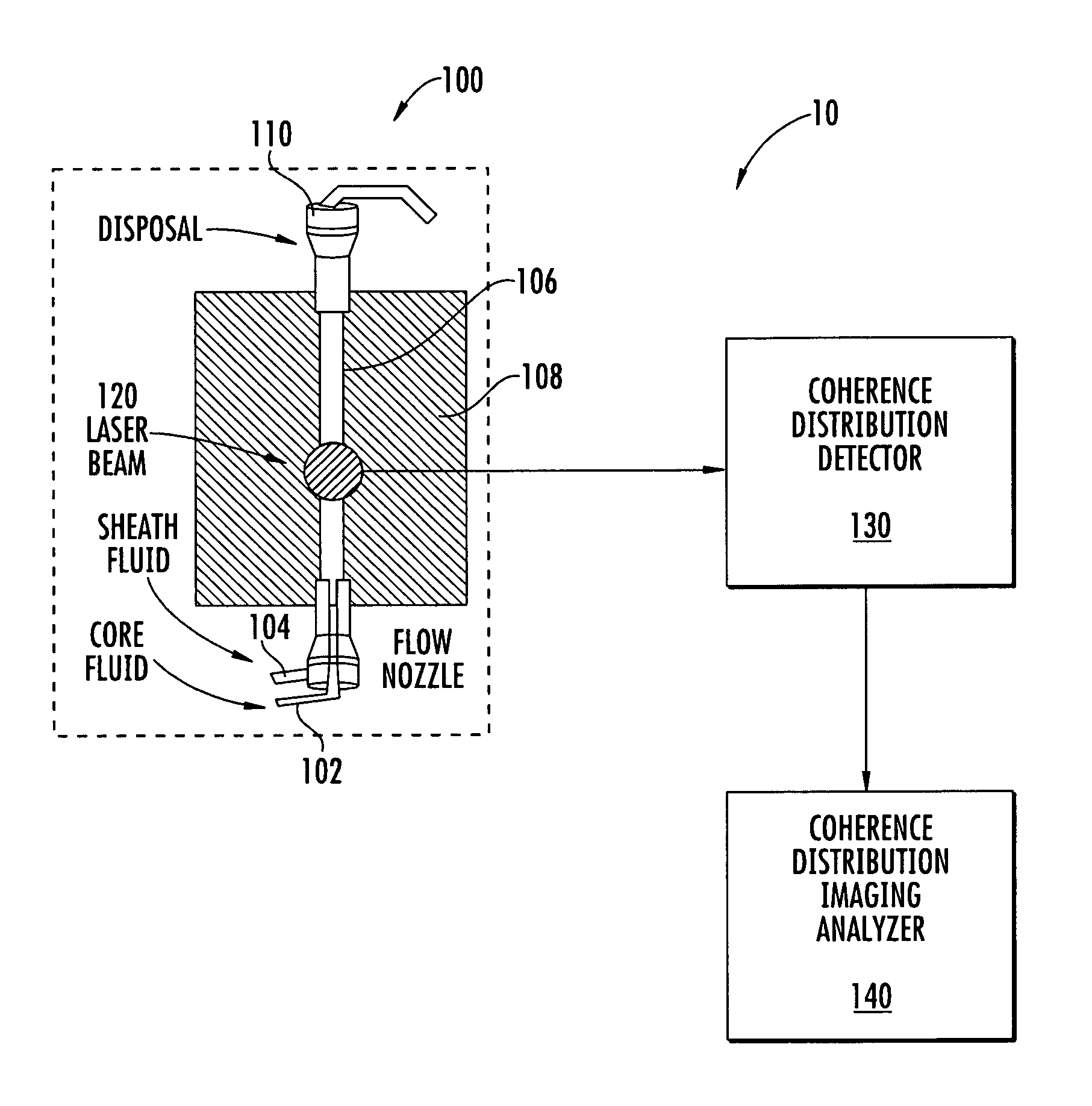
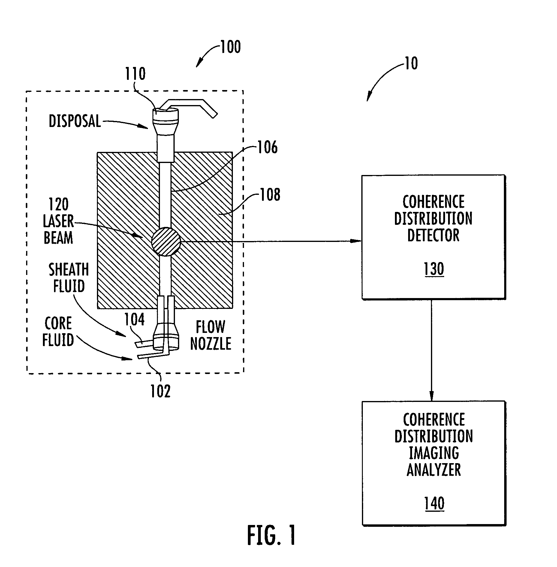
The present invention relates to a flow cytometer assembly and methods for analyzing particles in a flow cytometer to determine three-dimensional morphology parameters. The assembly includes a fluid controller, a coherent light source, a detector, and an analyzing module. The detector can detect the elastically scattered light from a particle in the inner core fluid and provide diffraction image data. The analyzing module can extract the three-dimensional morphology parameters of the particle by analyzing the bright-field and / or dark-field and / or fluorescence signals from the particle. The invention allows for the accurate analysis of particles in a flow cytometer and provides valuable information on their structure and morphology.

Problems solved by technology

However, these techniques rely on conventional fluorescence or bright-field microscopy in which the resulting images are non-diffractional and inherently two dimensional replicas of the three dimensional cell structure (with the third dimension being compressed into a “focal depth”).
Although these two dimensional images can be analyzed with pattern recognition algorithms, automated analysis with existing pattern recognition algorithms is complex, labor intensive, and challenging at least because of the two dimensional nature of the image.
However, this technique typically requires multiple images and, therefore, these confocal imaging techniques are generally not compatible with an imaging flow cytometer in which the particles are moving relatively rapidly.

Method used


Image

  • Flow cytometer apparatus for three dimensional difraction imaging and related methods
  • Flow cytometer apparatus for three dimensional difraction imaging and related methods
  • Flow cytometer apparatus for three dimensional difraction imaging and related methods

Examples


example 1

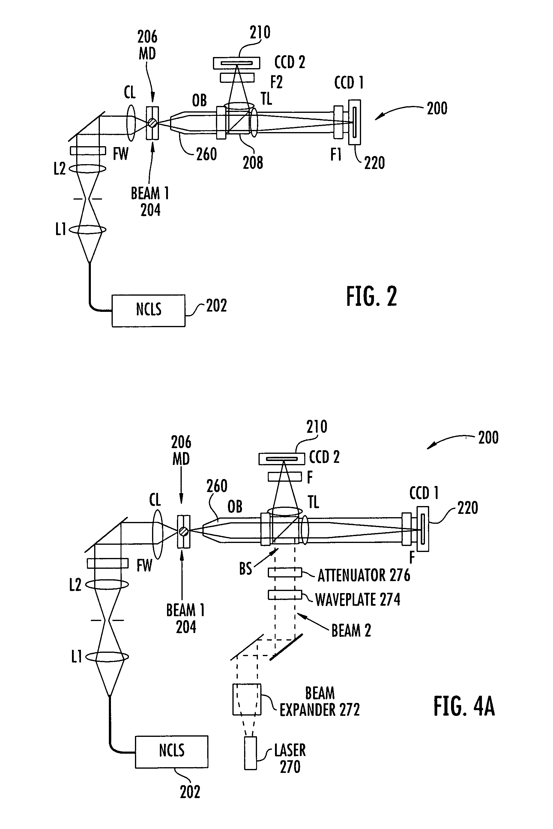
[0080]To increase the morphology information that can be retrieved from elastic light scatter due to excitation by a coherent light source, a prototype microfluidic flow cytometer was constructed to test the concept of diffraction image acquisition with a standard cooled CCD imager (Alta U2000). The prototype is shown in FIGS. 6a-6d. A preliminary study of diffraction images with polystyrene microspheres has been performed. The prototype can have the specifications as set forth in Table 1.

[0081]

TABLE 1The expected specifications of the proposeddual-image microfluidic flow cytometerAdjustable flow speed0.01~0.50 m / sAdjustable core fluid diameter20~150 μmHalf-width of angular region for diffraction image*32°Center of angular region for diffraction image5°, 45°-135°, 180°Lateral resolution of the non-diffraction image*0.4 μmField of view of non-diffraction image*320 μm × 240 μmCCD Camera exposure time10-10,000 μsImage frame transfer rate (251 × 250 pixels112 frames / sper image frame)SNR...

example 2

[0084]Coherent scattering of a monochromatic light beam occurs as a dominant form of interaction when the refractive index n becomes heterogeneous, n(r,λ), where r is the position vector inside a particle and λ is the wavelength for both incident and scattered light, shown schematically in FIG. 9. The scattered fields lead to the spatially coherent and characteristic scatter distributions which can be acquired as diffraction (spatial) or speckle (spatial and temporal) images. With accurate wave models based on the solution of the Maxwell equations or wave model trained pattern recognition software, it is possible to extract intra-particle refractive index distribution and thus three-dimensional morphology information of the scatterer or cells from the elastic light scatter distribution or diffraction image data. The intra-particle index distribution of n(r,λ) correlates with cell's morphology. (Ref: R. Baer, “Phase contrast and interference microscopy in cytology,” in Physical Techn...

example 3

[0087]Forty cultured NALM-6 cells in different cell cycles are selected as a cell model to establish a training database for cell classification. The cells are stained and imaged with a confocal microscope (LSM 510, Zeiss). The three dimensional structures will be constructed for two purposes. First, these structures will be imported into our FDTD code for simulations of angle-resolved elastic light scatter from the cell excited by a coherent light beam. Second, these structures will be analyzed to define multiple classes of morphology features as the basis for development of the pattern recognition software for cell classification. Light scattering by a single biological cell can be modeled as a plane wave incident on a dielectric scatterer in a host medium. To account for the polarization change associated with scattered light, a framework of Stokes vectors is adopted for the incident and scattered light fields and a Mueller matrix for the cell.

[0088]The incident light is represen...


PUM


Abstract

A flow cytometer assembly includes a fluid controller configured to form a hydrodynamically focused flow stream including an outer sheath fluid and an inner core fluid. A coherent light source is configured to illuminate a particle in the inner core fluid. A detector is configured to detect a spatially coherent distribution of elastically scattered light from the particle excited by the coherent light source. An analyzing module configured to extract a three-dimensional morphology parameter of the particle from a spatially coherent distribution of the elastically scattered light.

Description

RELATED APPLICATIONS[0001]This application is a 35 U.S.C. §371 national phase application of PCT Application PCT / US 2009 / 003508, filed Jun. 11, 2009, and published on Dec. 17, 2009, as International Publication No. WO 2009 / 151610 A2, and which claims the benefit under 35 U.S.C. §119(e) of U.S. Provisional Patent Application Ser. No. 61 / 060,993, filed Jun. 12, 2008, the disclosure of each of which is incorporated herein by reference in its entirety.FIELD OF THE INVENTION[0002]The present invention relates to flow cytometers, and in particular to flow cytometers for detection of three dimensional morphology parameters and imaging.BACKGROUND[0003]Flow cytometers are used in life science research for quantitative assays of large populations of biological cells and particles. A beam of light (typically of a single wavelength) is directed onto a hydrodynamically focused stream of fluid. The fluid stream typically includes a fluid carrier or “sheath” and a core fluid including a plurality ...

Claims


Application Information

Patent Timeline
IPC IPC(8): G01N21/00G01N15/02G01N15/14
CPCG01N15/1475G01N15/147G01N15/0211G01N2015/0222G01N2015/025G01N2015/1497G01N15/1433
Inventor HU, XIN-HUAJACOBS, KENNETH M.LU, JUN O.
Owner HU XIN HUA
Learn More