
Method and UHT installation for treating heat-sensitive liquid food products

a technology of heat-sensitive liquid and food products, applied in the field of heat-sensitive fluid food products treatment, can solve the problems of high investment cost, low vitamin loss, complicated process technology, etc., and achieve the effect of increasing pressur

Active Publication Date: 2015-04-21
GEA TDS
View PDF5 Cites 6 Cited by
  • Summary
  • Abstract
  • Description
  • Claims
  • Application Information

AI Technical Summary

Benefits of technology

[0023]The pressure increase according to the invention works against a boiling out of the food product and the associated release of gas, on the one hand. And on the other, the gas release of non-dissolved gas components and release of non-condensed steam is reliably prevented, particularly because without this pressure increase the food product would like at or near the boiling point.
[0024]It is known that gas release in so-called heat maintenance that is not heated from outside and that extends up to the previously mentioned relief, and here on the walls of the heat maintenance, leads to increased burning of the food product and deposits with significantly faster deposit speed, the protein fouling described above, which necessitate cleaning of this area at much shorter intervals than would be the case if such gas release were avoided.
[0025]The planned pressure increase is achieved with the conventional displacement pump in the UHT system, whose function was limited until now to accurate regulation of the dwell time and the flow of the product. The volume flow / pressure characteristic of such a displacement pump decouples the system pressure downstream of the pump from that upstream, so that the working conditions of a system in which the food product is subjected to direct heating by introduction of steam, namely the pressure and the volume flow, are uniquely defined. Furthermore, the displacement pump, regardless of whether it is implemented as a rotating or oscillating pump has a greater or lesser self-cleaning property, whereby either the coating on the wall surfaces moistened by the food product is prevented even during its formation, or coatings that do form are continually carried away.
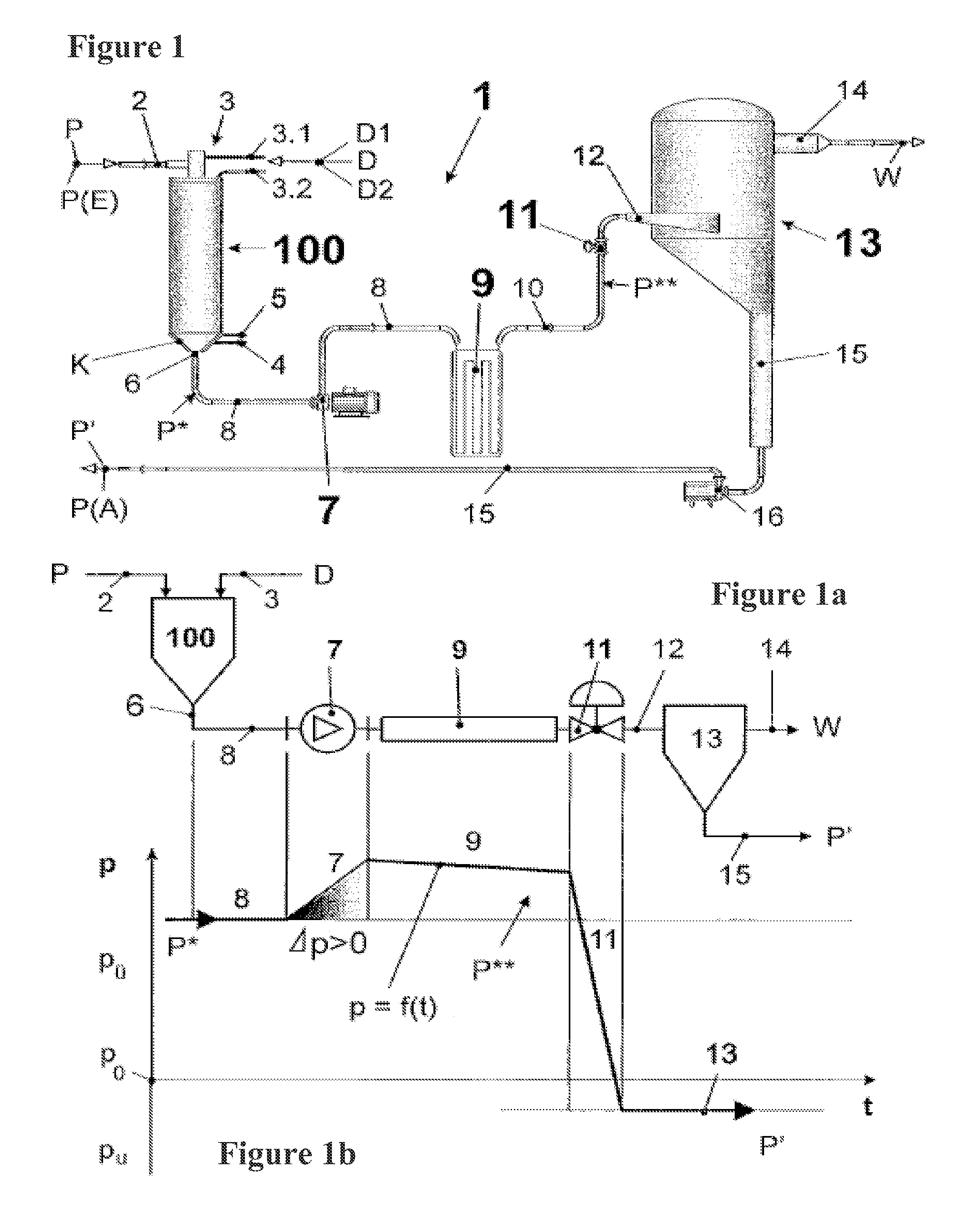
[0031]Since UHT systems with either injector or infusion chamber each specify a defined volume following, the dwell time of the food product at the relevant heat maintenance level between the displacement pump and a relief valve that effects the necessary relief of the heated food product is equally defined and predetermined by the cross-section of the transition and the implemented and easily changed flow path in this area. Moreover, the temperature drop only takes place in the relief valve, whereby according to an advantageous embodiment of the UHT system this valve can advantageously be placed directly before the inlet to a vacuum chamber and thus degassing effects can no longer disadvantageously occur in the line, but rather in the vacuum chamber provided for this purpose.
[0036]The relief valve is advantageously placed directly before the inlet into the vacuum chamber, so that degassing effects can no longer take place disadvantageously in the line but rather in the vacuum chamber provided for that purpose.

Problems solved by technology

Moreover, the vitamin losses are low after gentle heat treatment, that is, with relatively short heating and duration such as those provided by high-temperature and short-term heating.
The disadvantage of the infusion process in comparison with the injection process is its complicated process technology and higher investment costs.
In all the heating processes outlined so far, regardless of whether it is an indirect or a direct heating process, there are more or less severe deposits particularly in the heater part and in the downstream heat maintenance section not heated from outside or the downstream heat maintainer not heated from outside, leading to quality problems in the food product and / or to serious cleaning problems, whereby the latter require extensive cleaning times and thus shorter working times for the UHT system and special cleaning procedures and agents.
The dwell time and temperature curve of the heated milk, starting from its entry into the infusion chamber until its exit into the vacuum chamber, are not sufficiently predetermined in conventional UHT systems and they cannot be controlled uniformly for all the milk portions introduced, since the conveying and control mechanisms that would be needed for this purpose are absent and no specifications can be made or expected in this sense.
Moreover, if the product is in the vicinity of the boiling point, its gas content and uncondensed steam can lead to deposits, frequently associated phase separations, and thereby to increased burning, accelerated formation of coatings, and negative quality changes in the product.
Boiling out of the product cannot be prevent if it is at or near the boiling point.
Since the centrifugal pump cannot effectively decouple the pressure in the system between the centrifugal pump and the expansion valve from the pressure before the centrifugal pump and thus in the infusion chamber, the fill level and thus the dwell time and the temperature in the parts of the system upstream of the centrifugal pump cannot be exactly controlled or defined.
The duration of heat maintenance is therefore determined by the pump layout, whereby simple variable adaptation to different operating conditions, process requirements, and food products is more difficult.
Since no mechanical changes to the flow can take place in the connecting line downstream of the displacement pump, uncontrolled dwell time effects can be anticipated there that also have negative effects on the quality and formation of fouling.
Thus between the infusion mechanism and the relief valve there is a forced pressure drop due to flow and friction loss and the displacement pump is limited to controlling the dwell time and the flow of the product precisely.
Thus even this known UHT system provides for a forced pressure drop caused by a flow and friction loss between the infusion chamber and the downstream end of the heat maintenance section, and the control pump is restricted to the accurate regulation of the dwell time and the flow of the product.

Method used


Image

  • Method and UHT installation for treating heat-sensitive liquid food products
  • Method and UHT installation for treating heat-sensitive liquid food products
  • Method and UHT installation for treating heat-sensitive liquid food products

Examples


first embodiment

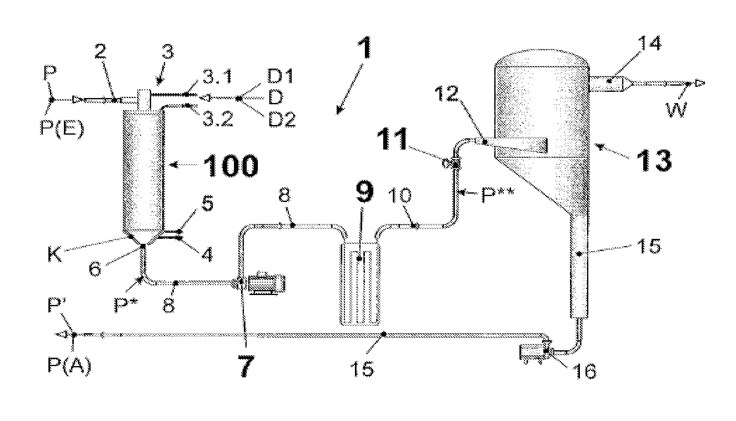
[0056]Due to the system characteristics of the UHT system 1 in the first embodiment as described above, the process characteristic according to the invention can be implemented that consists of the fact that the heated food product P*, before its heat maintenance as seen in the flow direction, undergoes a predetermined pressure increase Δp at a predetermined, unchanging location with the goal described above. This location, independently of fluctuations in operating conditions and due to the special displacement pump characteristic that achieves a decoupling of the system pressures p upstream and downstream of the displacement pump 7, is permanently at the suction-side inlet of the displacement pump 7 and thus, due to the preferably narrow and direct connection of the latter to infusion chamber 100, also at outlet 6.

second embodiment

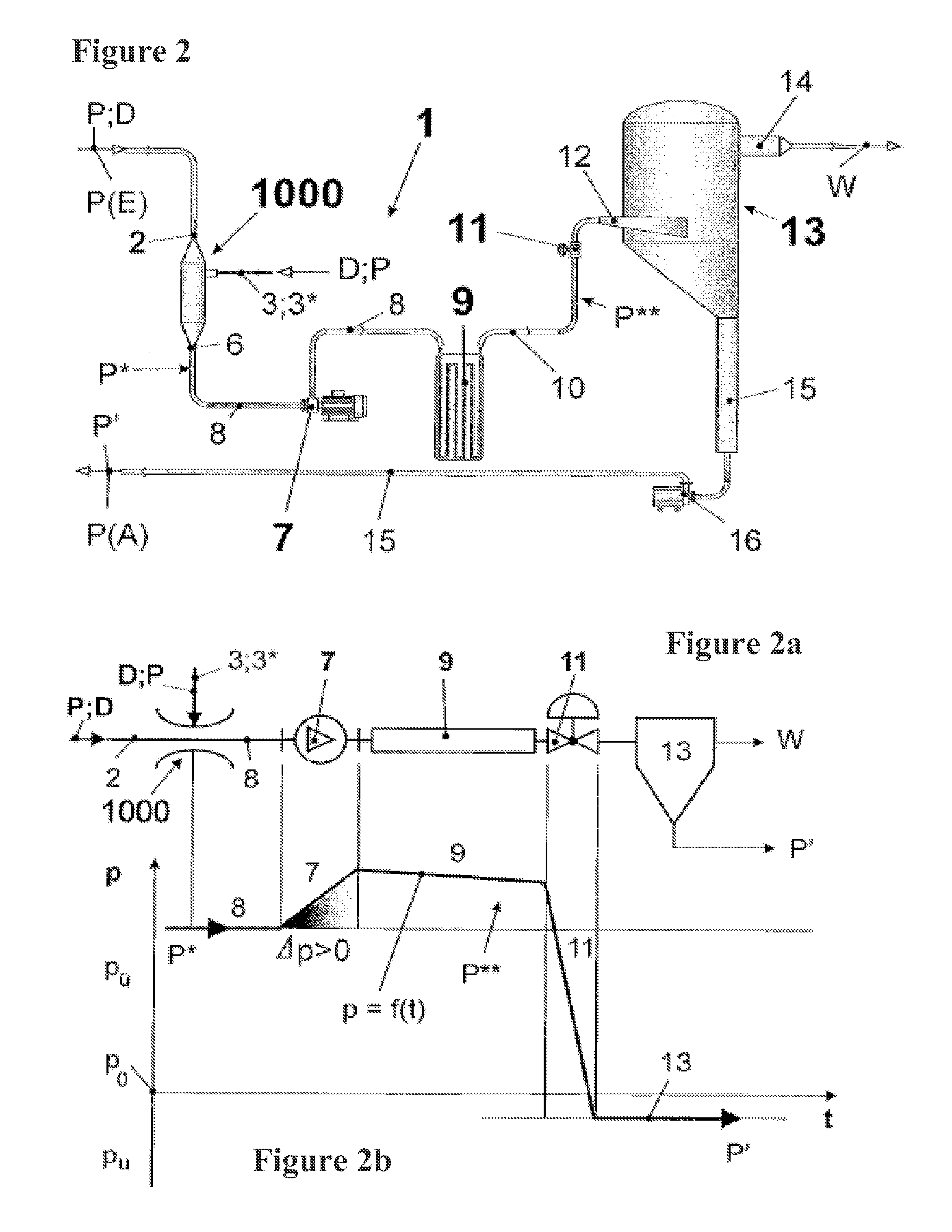
[0057]the UHT system 1 according to the invention (FIGS. 2, 2a, 2b) differs from the first shown in FIGS. 1, 1a, and 1b in that the mechanism in which the food product P to be treated is subjected to direct heating by means of introduction of steam D is now implemented according to the invention as an injector 1000. The other components of the UHT system 1 as shown in FIG. 1 are, insofar as they do not directly belong to infusion chamber 100, embodied identically in the second embodiment and have the same corresponding effects there. We will therefore forego a description.

[0058]The injector 1000, in a first embodiment, has on the one hand an inlet 2 for the introduction of the food product P to be treated, which leaves it on the other hand at its outlet 6 as the heated food product P*. A steam inlet 3 is used to introduce the steam D needed for direct heating, whereby steam D flows into the food product P acting as the driving stream. This first embodiment is therefore characterized...


PUM


Abstract

The invention concerns a process for the treatment of heat-sensative fluid food products (P) in a UHT system (1), particularly dairy such as milk, cream, milk protein concentrate. The invention has the task, in a UHT system whose basic structure using an infusion chamber is described in [4], of ensuring an equal and constant dwell time as well as an equal and constant temperature trend for the entire treated food product downstream of an outlet of a mechanism in which the food product is subjected to direct heating by the introduction of steam, and to minimize fouling during heat maintenance of the food product in this area. This is achieved using process technology in that:The heated food product (P*) upstream of its heat main undergoes a predetermined pressure increase (Δp) at a predetermined, unchanging location, andThe pressure level upstream of the location before the relief lies above the pressure upstream of the location before the pressure increase (Δp) (FIG. 1).

Description

CROSS-REFERENCE TO RELATED APPLICATION[0001]The present application claims the priority under 35 U.S.C. 119 of German Patent Application No. 10 2010 008 448, filed on Feb. 18,2012, which is hereby incorporated herein by reference in its entirety.TECHNICAL AREA[0002]The invention concerns a UHT system for the treatment of heat-sensitive fluid food products, particularly a dairy product such as milk, cream, milk protein concentrate, or buttermilk, using a system in which the food product is subjected to direct heating by means of the introduction of steam, with a vacuum chamber in which water is extracted from the food product, with a line for the food product connecting an outlet of the system to an inlet of the vacuum chamber, with a first conveying mechanism located downstream of the system in the line and with a relief valve located downstream of the first conveying mechanism in the line. The invention also concerns a process for the treatment of heat-sensitive fluid food products...

Claims


Application Information

Patent Timeline
Patent Type & Authority Patents(United States)
IPC IPC(8): A23L1/00A23C3/037A23L3/16A23L3/18A23L3/22
CPCA23C3/037A23L3/16A23L3/18A23L3/22
Inventor KOWALIK, MANFREDTACKE, LUDGERLEIWERING, LUDGERSCHWENZOW, UWEZIMMERMANN, DIETRICH
Owner GEA TDS
Learn More